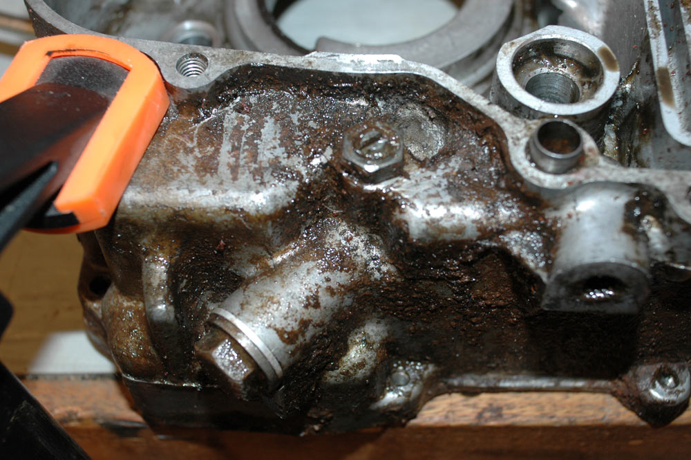
Engine number one. Cases are pretty corroded.
The Wenga Postie Bike Project -> The rebuild -> Engine
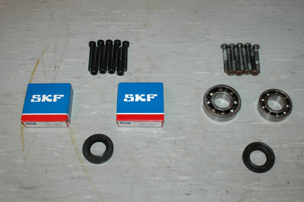
I have three engines, and two gasket kits. One engine has points ignition (pre-82 I believe), and the other two are CDI engines. My aim is to build up a CDI engine for the bike we'll keep, then see what other one I rebuild. I'll part the last engine out via fleabay at an appropriate time.
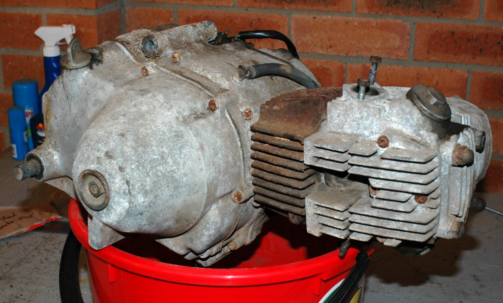
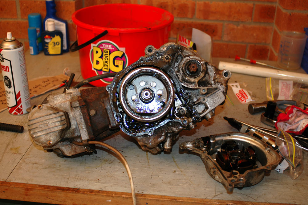
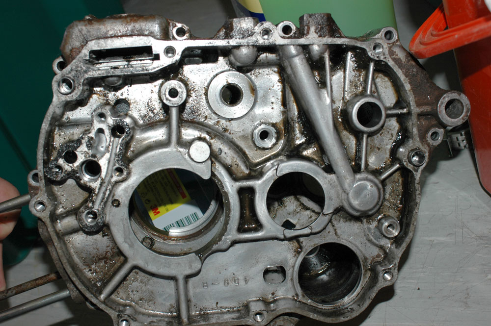
Here's engine number one.
Engine number one. Cases are pretty corroded.
I chose this one first because it is a CDI motor, but the cases are shagged. This means I can be a bit rougher with the first attempt to pull stuff apart and not worry about the cases so much. The motor I probably want to use for the bike we're keeping has rusty rockers & a few other things, so I think the internals from engine #1 will be used (at least in part).
To pull a motor down, you start by draining the sump. This motor hasn't had an oil change in a fair while, so what came out was sludge. I gave it an entire night to drain (and as you can see from the later pictures, it didn't drain that much!)
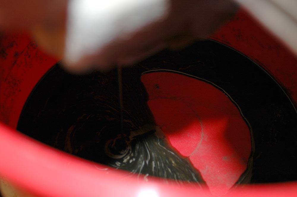
SumpSludge. Lovely.
Pulling these motors apart isn't that hard at all. I'll start with the flywheel side.
To undo the flywheel cover, you start by loosening off the screws. Even on a fresh motor they're stubborn and will require some kind of penetrant plus an impact screwdriver. Learn to love your impact driver - they are absolutely required for these motors.
Removing the flywheel cover screws.
I'll have an aside now for a few comments about impact drivers. Make sure your impact bits are the right size for the screws - impact drivers can easily round off a screw head. You'll also want to verify which way your driver turns: read the instructions for this. When you hit a driver, smack the back of it like you intend to break your hand if you miss the driver head. If you don't do that, you won't hit it hard enough and you won't undo the screw. For really locked-in screws, keep trying and you'll eventually undo the screw. Or break your hand. Or destroy the screw. Or break the impact driver.
Once you've loosened all the screws on the cover, use a normal screwdriver and remove them. With luck the cover will come off easily - don't try to prise it off or you'll mark the surface of the cases and it'll leak oil from then on. If you can't get it to budge, tap it with a plastic or rubber mallet. The only sticking point I found was the gear lever poking out the side (the lever is slightly bent on this motor) and the pull of the magnetised stator.
Here's the flywheel cover removed from the engine.
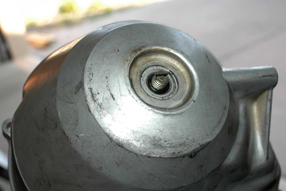
Now it's time to remove the flywheel. First off, there's a nut in the middle - 17 or 19 mm, I forget (probably 19).
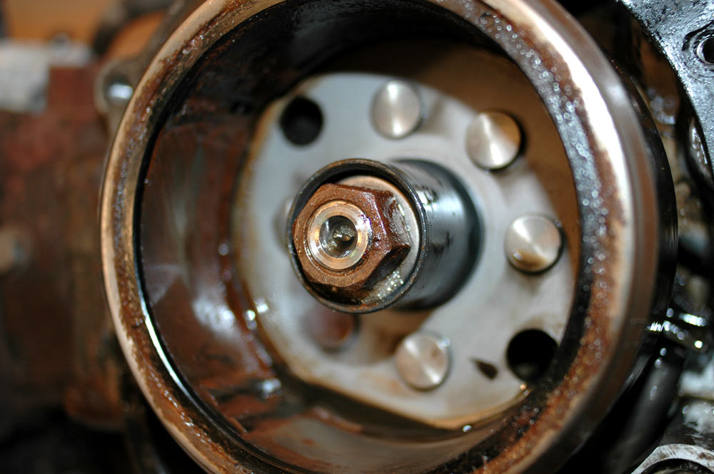
Here's the nut in the middle of the flywheel.
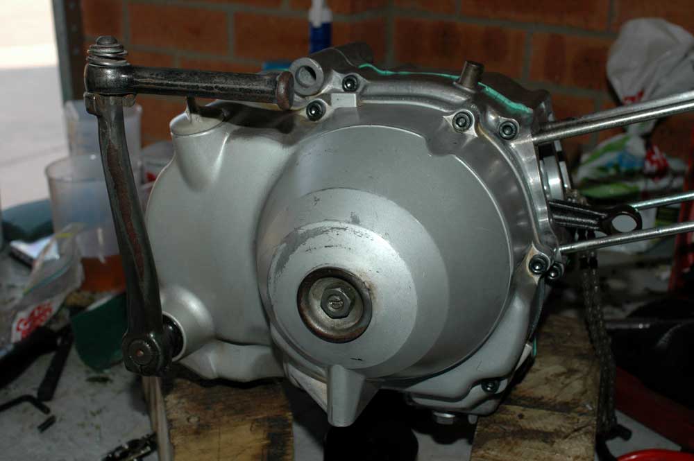
You can undo this either the hard or the easy way. The hard way is to hold the flywheel still with a strap or something, and undo the nut normally. The easy way is with impact sockets plus a rattle gun. Guess which one I chose?
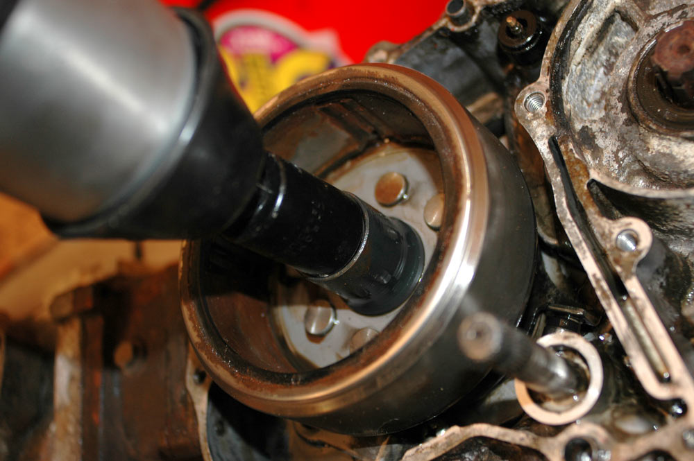
Undoing the flywheel using a rattle gun.
Once the nut is removed, you can see a thread on the inside of the centre part of the flywheel. This is where you screw in a suitable flywheel puller. From memory, the thread into the flywheel is 27x1.0L (i.e. left-hand thread).
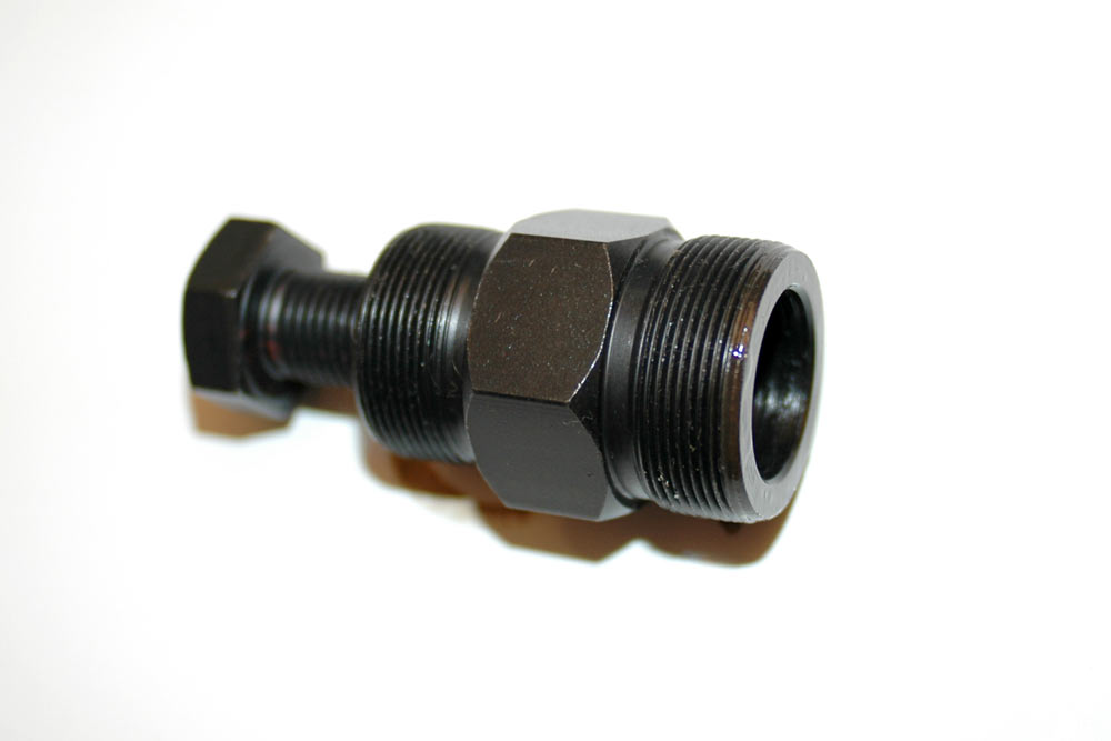
The flywheel puller I purchased for this job. Large thread is 27x1.0L; bolt through centre is tightened up so it contacts the end of the crank when the large thread is screwed into the centre of the flywheel.
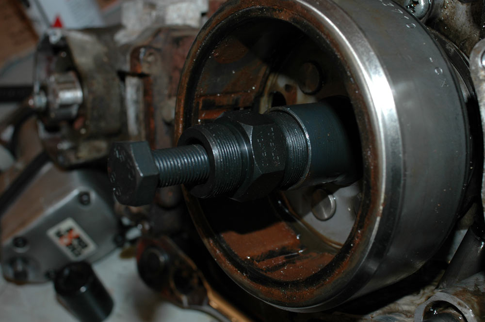
Flywheel puller screwed into centre of flywheel.
You now hold the flywheel with a strap or chain pliers, also hold the body of the flywheel puller (in my case, with a 32 mm spanner), and use a 19 mm spanner to turn the bolt through the middle of the puller. The flywheel should slide off the crank easily. If it doesn't, DO NOT HIT THE FLYWHEEL but instead tap the bolt through the middle of the puller. You can also try getting a bit of WD-40 down between the crank and the flywheel.
Holding the flywheel still. Chain pliers aren't actually done up that tight so they didn't mark the flywheel sides. It takes three hands to hold everything that you need to in order to pull the flywheel off.
Once removed, the flywheel and crank behind it will look like this:
Flywheel removed.
Fairly obvious in the above photo is that I've also removed the CDI cover. It's not very hard to do this, you just need to undo the two screws with your trusty impact driver. I also removed the one screw which held the electrical pickup for the CDI unit.
To remove the CDI 'sender' (for want of a better word) and the ignition advance mechanism, you start by undoing the retaining ring plus the bolt which attaches the sender to the camshaft end.
Removing the CDI advance mechanism. I've already undone one screw, the second one can be seen in the bottom of the housing. They're the two screws which screw down onto the gold-coloured ring.
You then pull off the sender, then the ring and the advance mechanism. I'd take a shot of the advance mechanism but on this engine it was so rusty it fell apart. Bugger. I guess that means I'm building one CDI engine and one with points? After pulling out the advance mechanism, there are three screws which secure the housing to the head - pull them off too.
Now it's time to pull out the camshaft. Undo the two bolts holding it to the timing chain sprocket. It takes a bit of wiggling, but you can pull it out assuming you set the engine to TDC with slack on both valves (pretty sure that's TDC after intake, actually).
Removing the camshaft.
As you pull out the camshaft it's not a bad idea to push a screwdriver in to stop the timing chain and sprocket disappearing a fair way down.
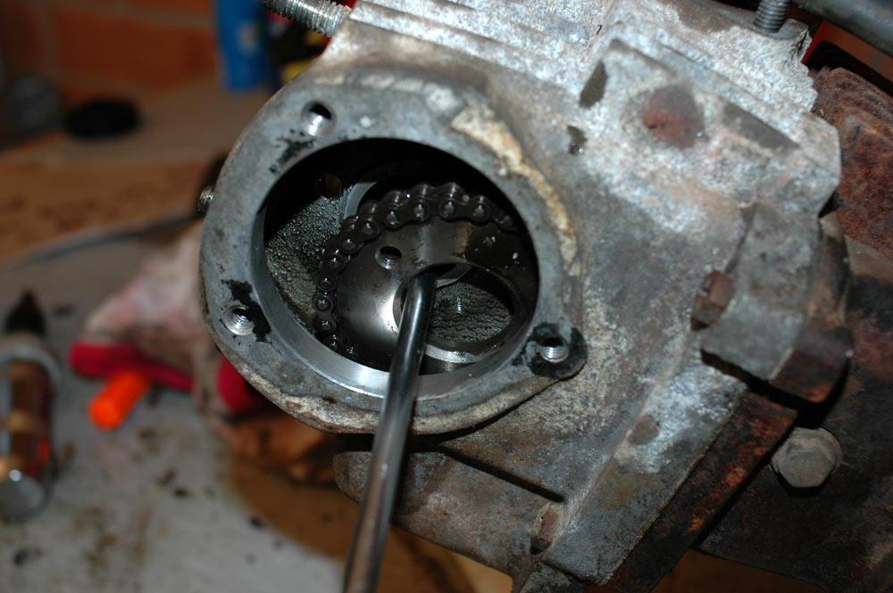
Holding the timing chain sprocket with a screwdriver.
Now we can remove the head. Undo the four nuts on the top cover and take the top cover off. There are also two screws holding the head to the cylinder (you can see one in the above photo). Undo these two - ntoe that although they have screw heads as well as normal bolt heads, you can't get a screwdriver in to undo them, so just undo them with a spanner (they're 10 mm). Tap the head with a rubber mallet or something similar, and pull it off the studs.
Removing the head. Note that I've now let the timing chain sprocket down into the head.
With a bit more wriggling, the head will come right off.
Head removed!
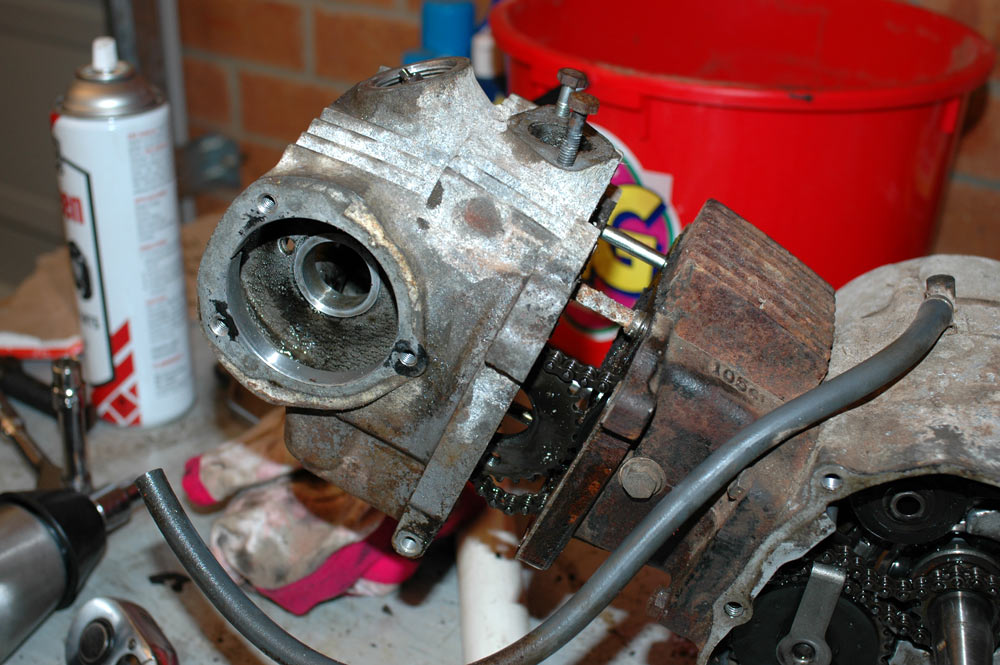
Not too much more effort to remove the cylinder. Undo the bolt that you can see in the side of the cylinder, as it holds an idler pulley for the timing chain. There are also two bolts that hold the cylinder to the cases, which you can see in the above photo. Undo them too. Tap the cylinder and pullllllllllllllll...
Removing the cylinder.
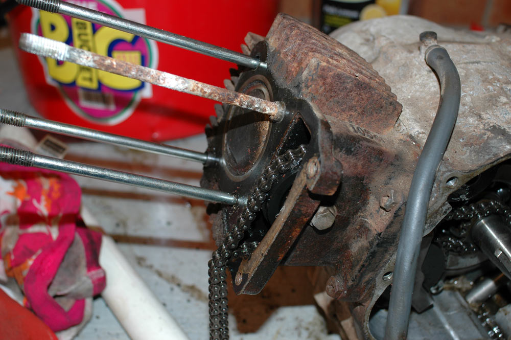
You can now undo all the screws which hold all of the timing chain gear and remove the timing chain. There are two screws which hold the timing chain idler sprocket (bottom one), and another which holds the timing chain tensioner. Pull all of that off, and store it somewhere safe.
Timing chain removed.
Alas, all this effort had its strain on my impact driver, so I had to wander out and buy another.
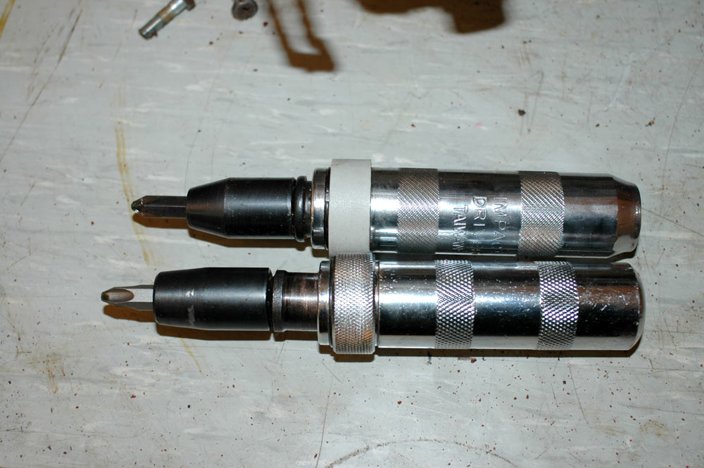
Top one is broken - it won't extend any more.
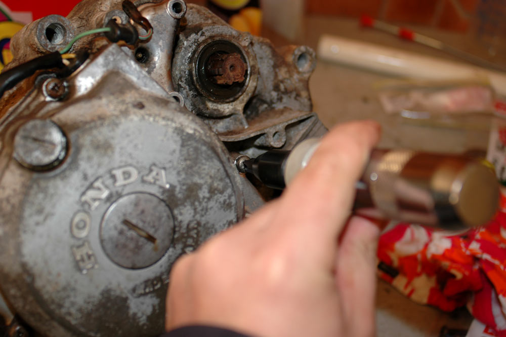
Time to attack the clutch side. First start by soaking any screws in some form of penetrating lubricant.
Soaking the clutch cover screws.
Attack the screws with the impact driver, just like the flywheel cover. Once they're all undone, get the cover off. This side was a bit stubborn so I had to use a rubber mallet. Note that this is the side that you need to take off to service the motors properly (there is an oil screen behind it in lieu of an external oil filter) and so I'd conclude this motor hasn't really had the best of servicing.
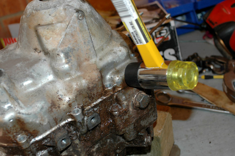
Tappity tap tap tap to get the clutch cover off.
Unfortunately, undoing the cover helps to unleash goop in the case of old engines.
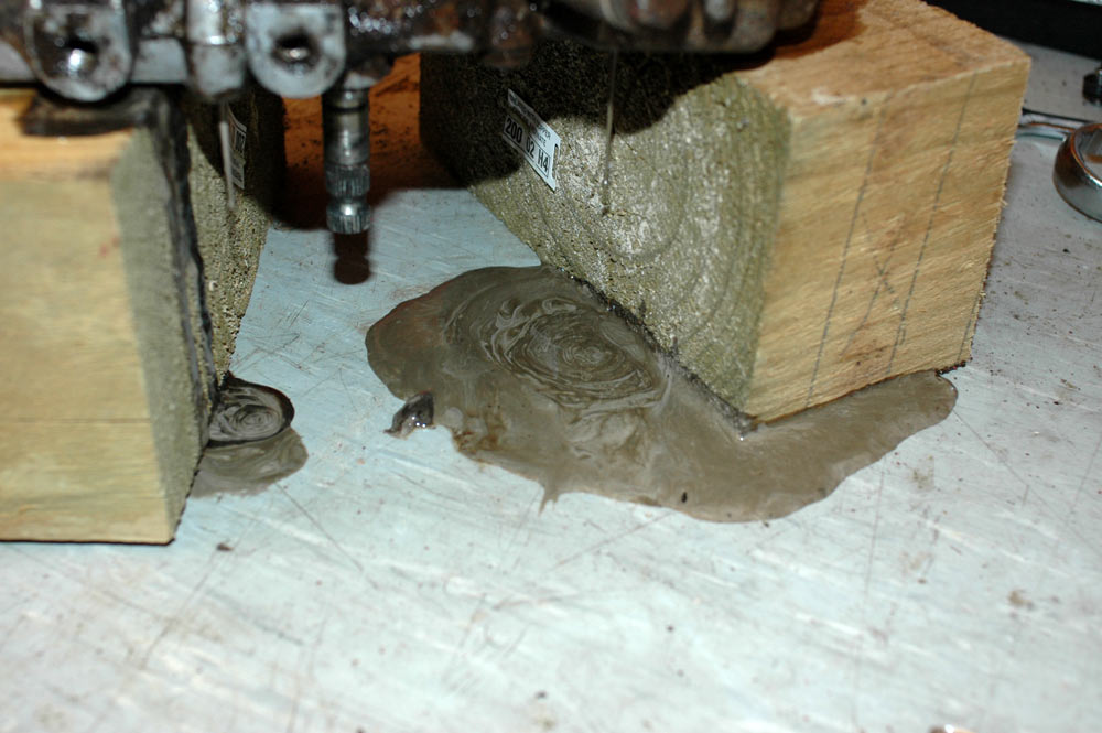
Extra goopy.
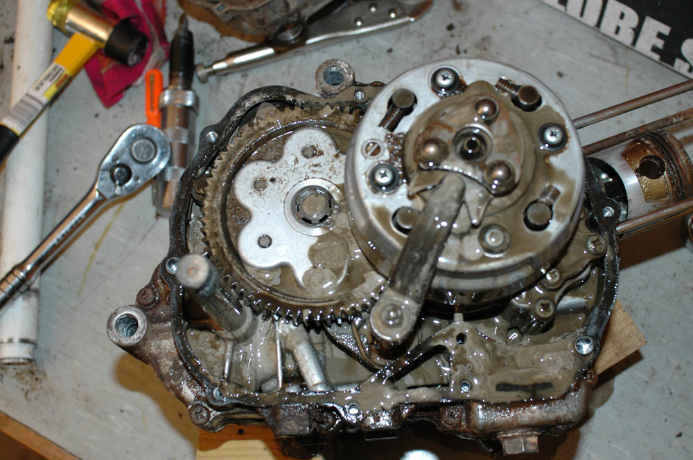
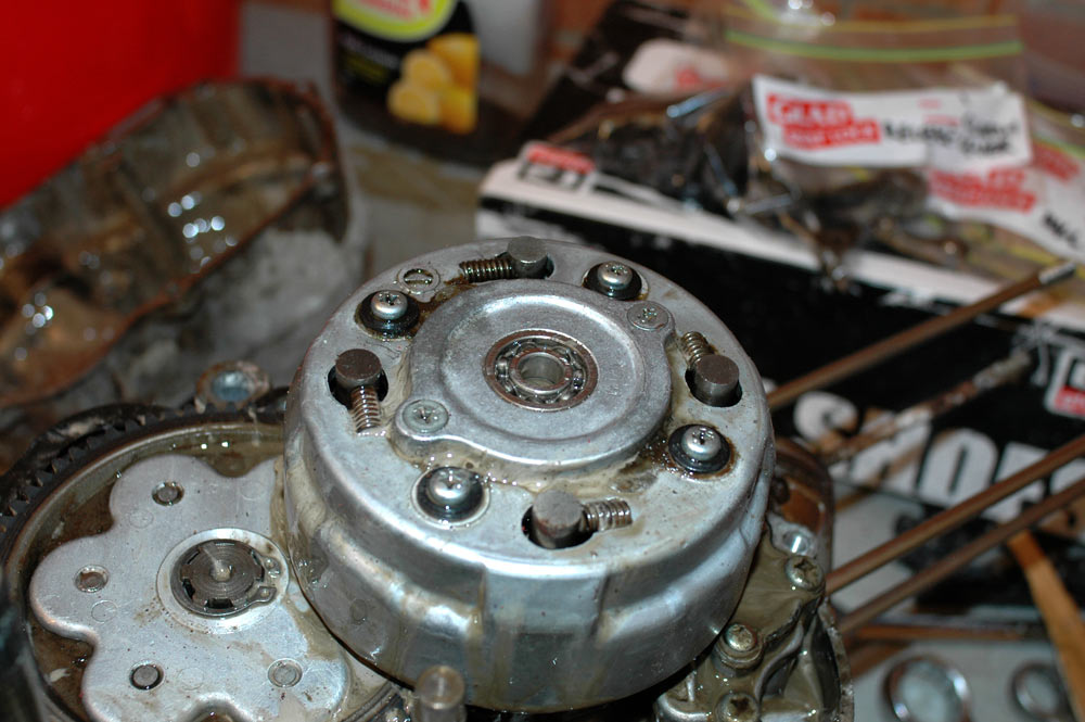
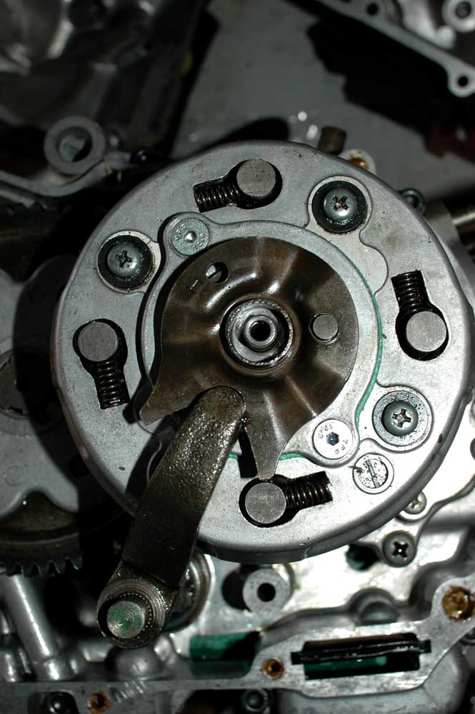
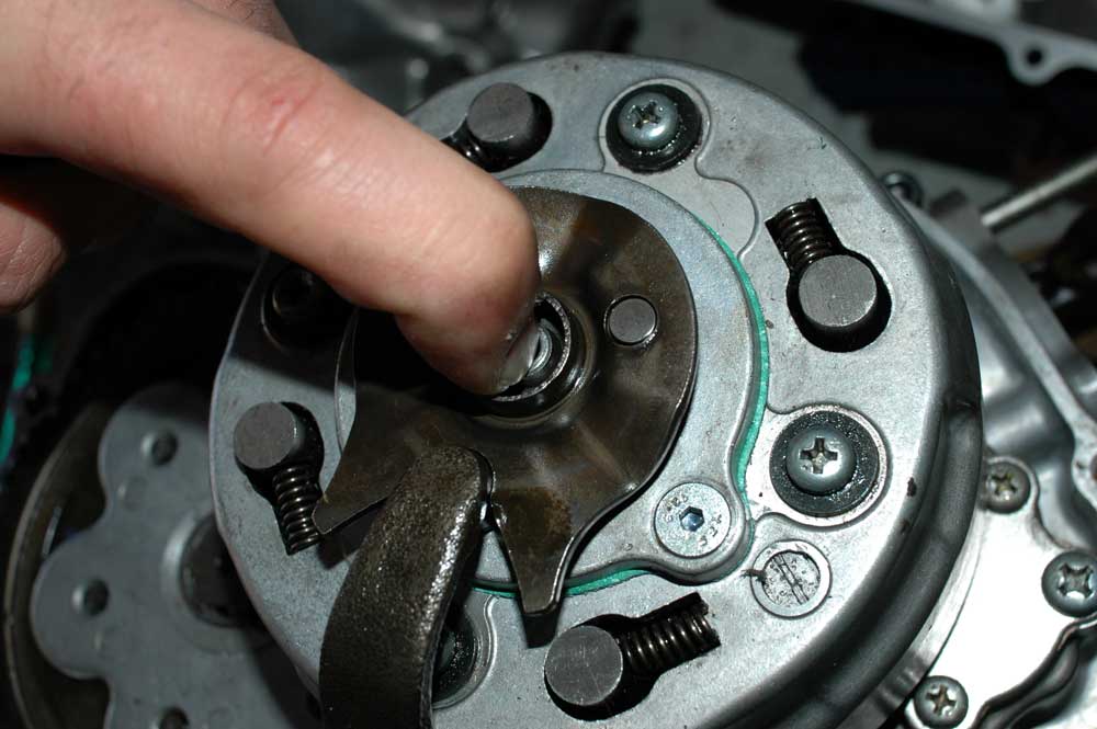
The beauty of the primary gear and the clutch mechanism.
Underneath the cover you'll alsofind the beauty that is the CT110 centrifugal clutch. The clutch actuating lever links up with the gear lever: press the gear lever down or pull it up and it'll disengage the clutch. The ball retainer thing sitting on top is what controls the centrifugal part - the locknut and screw on the outside of the clutch cover is what you use to set the clutch tension and hence what engine revolutions above which the clutch engages.
Remove that ball retainer sucker.
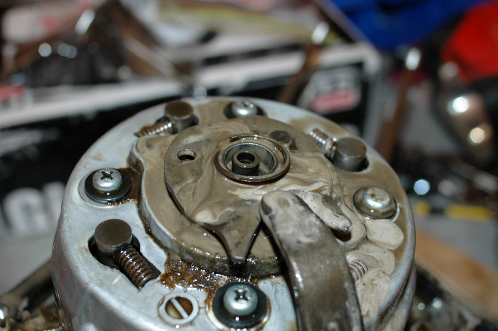
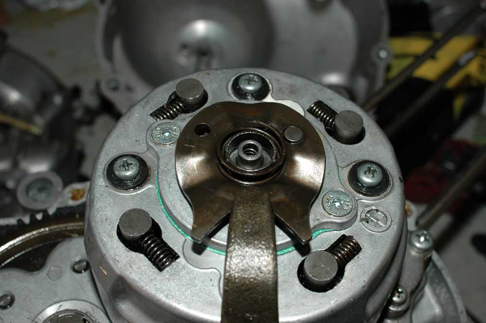
The ball retainer removed.
You can also pull off the spring and the bit the actuating lever operates on. This will reveal the front cover of the clutch basket.
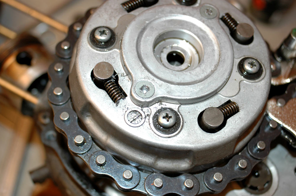
Clutch outer plate and bearing.
Unfortunately on this engine no amount of bashing or swearing removed the plate. In the interests of science and actually getting the damned thing apart, I drilled out the screws. Slight damage to the clutch basket, however, new ones are cheap & I probably need a whole new clutch assembly anyway given the amount of goop in this motor.
On the second engine, I was able to undo one screw with a screw extractor. Simply drill an appropriate pilot hole in the screw...
Drilling pilot hole in clutch outer cover screw.
... insert screw extractor and turn to the left using the provided tap T-handle.
Removing the screw with a screw extractor.
Considering these were cheapo screw extractors from a discount motor store, that's pretty awesome. Alas, a snag with the second screw: I snapped off the end of the impact driver bit in the screw head and couldn't budge it.
Argh! You bastard! Snapped off impact bit in the second screw.
So, that's two outer clutch covers I've destroyed in the process of rebuilding these engines. Second engine clutch outer cover survived though!
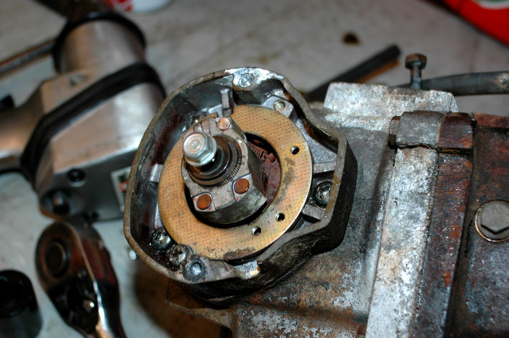
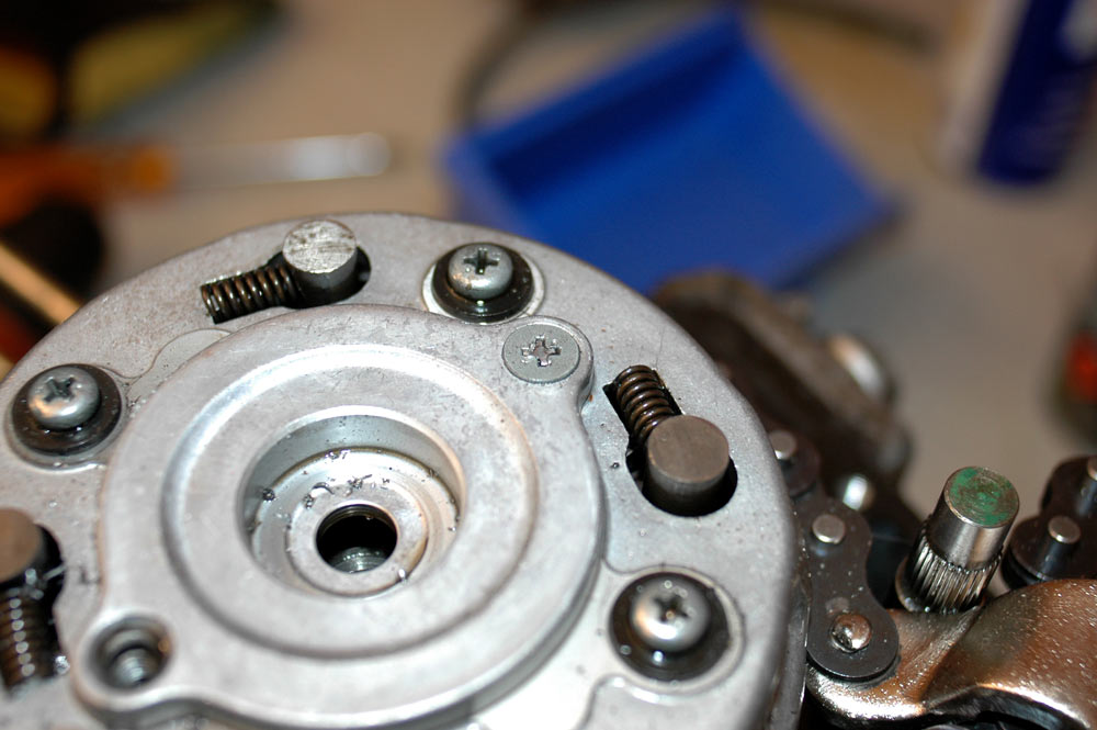
Once the clutch outer plate is removed you can see the clutch retaining nut. It requires a four-post retaining nut tool, which I do not possess. Also note the lock washer tabs.
The clutch retaining nut and tabs for the lock washer.
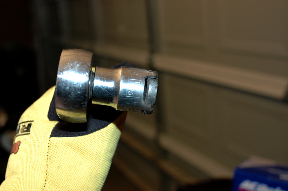
Rather than buy a clutch tool (when I didn't even know the required size - seems that it is 21 mm), I made one. Grab a 13/16" 1/2" drive Stanley socket and a small rotary tool.
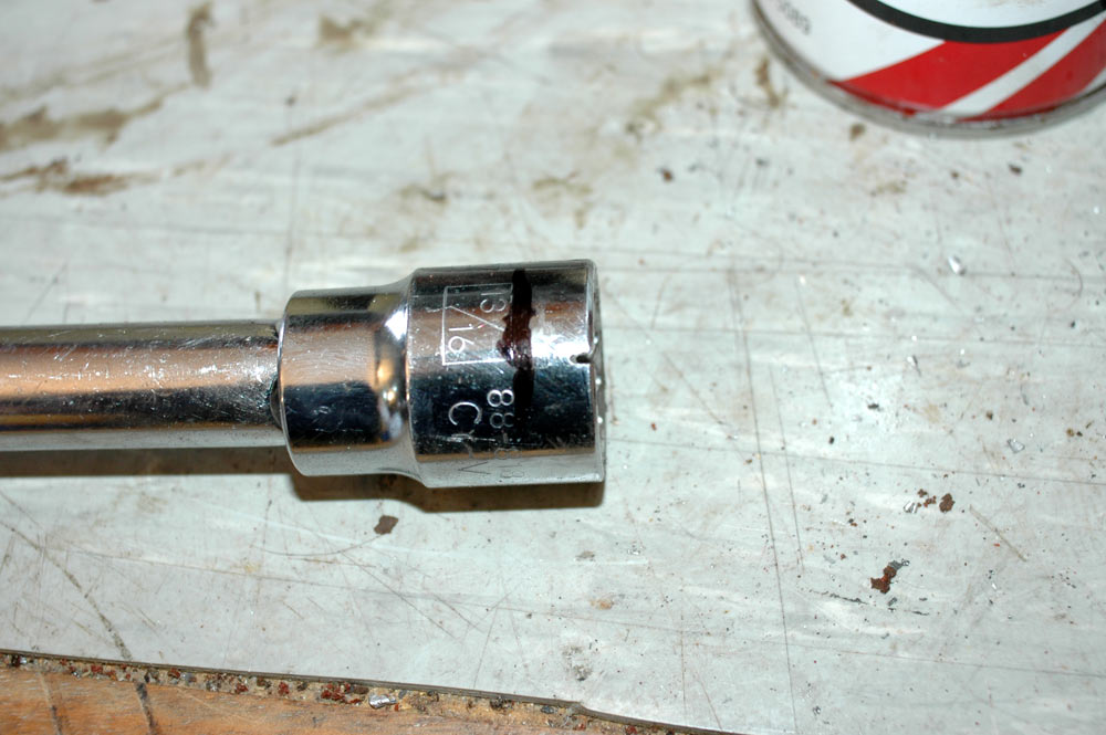
Socket donated for clutch retaining nut tool.
As you can see above, I made sure the rotary tool could cut the socket before I started. It was now time to get arty on the socket.
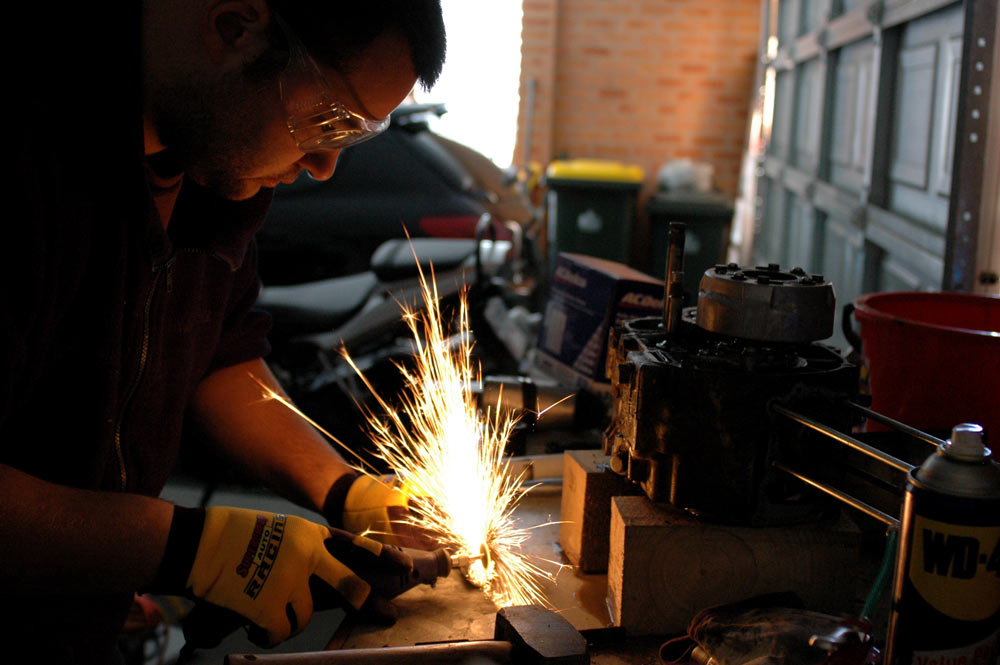
Making the clutch tool.
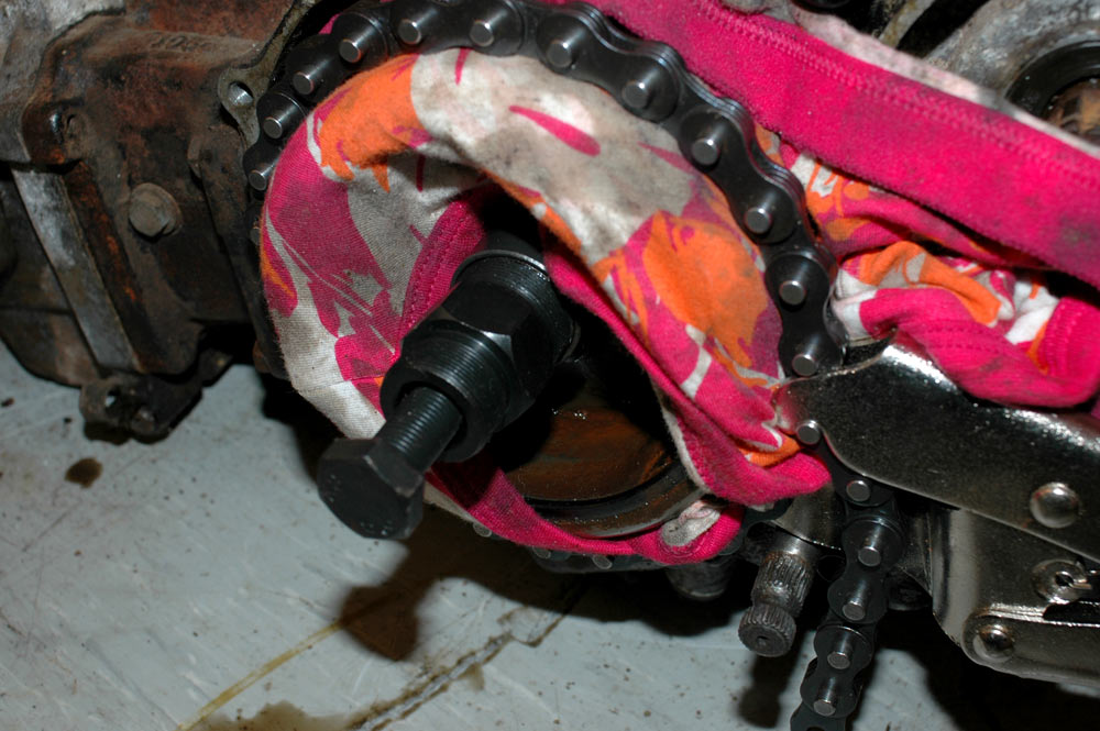
A small note about the gloves. Yes, they look poofy, but they were cheap and they do work. I've got sick of trying to pick all the grease out from under my fingernails when I go to work, plus with the gloves I can take one off and operate my camera without getting any grease on it.
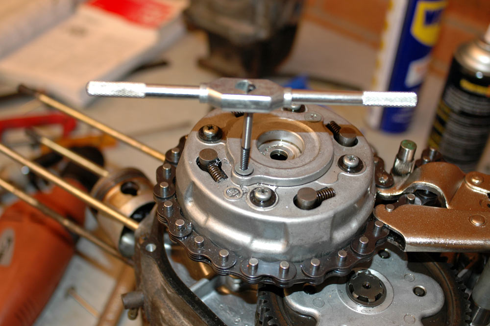
With the tool made, all you need to do is bend back the lock washer tabs, find some way of holding the clutch still, and undo the nut. To hold the clutch still I used the chain pliers, mainly cause I'd already munted the basket by drilling out the screws. You could also use a copper washer or if you're a Septic, chuck a penny in between the primary gear and the clutch drive gear.
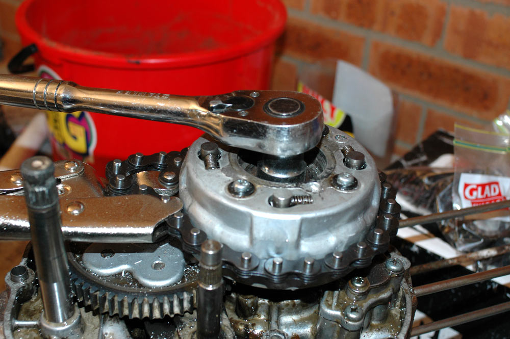
Undoing the clutch nut.
With the nut out, it is time to show off the majestic tool.
Clutch retaining nut tool, holding the clutch retaining nut.
Here you can see I wanted to get it done quickly - normally I'd dispense with the glove and show off my manly skin.
The oil pump is next.
There are a few screws to undo with your trusty impact driver, and one bolt just to make it different. I believe the big screws are needed to be undone to remove the whole oil pump, but if you just wanted to check it in situ then you'd pull off the two small and two big screws on the front oil pump cover.
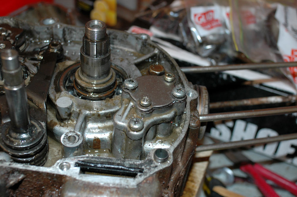
Removing the oil pump. Below it you can see the black end of the oil screen - you remove this oil screen if you wish to clean it when servicing the bike.
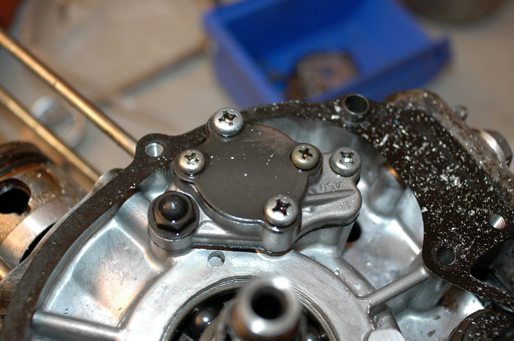
Oil pump prior to disassembly.
Time for a quick view of the clutch release mechanism. The rod that actuates the clutch actually goes the entire way through the cases to the other side. Up top left is the gear selector stuff.
Clutch actuator and gear selector linkage.
You need to undo a couple of bolts here to pull this apart - it's fairly evident with the engine in front of you what you have to do. My workshop manual states that if you can't pull the clutch acutator/gear shift rod all the way out through the cases then it is most likely due to a bent gearshift shaft and you should hack the gearshift shaft off on the flywheel side rather than destroying the cases pulling a bent rod through. Mine came out with a bit of wriggling.
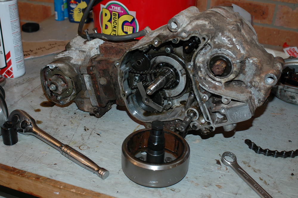
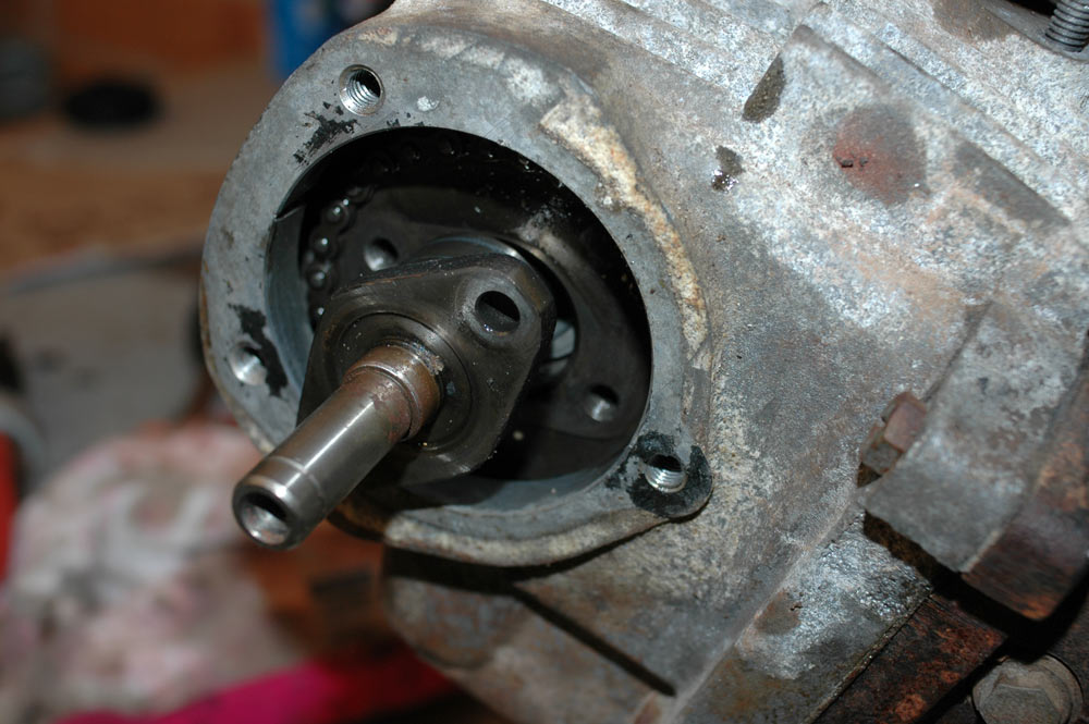
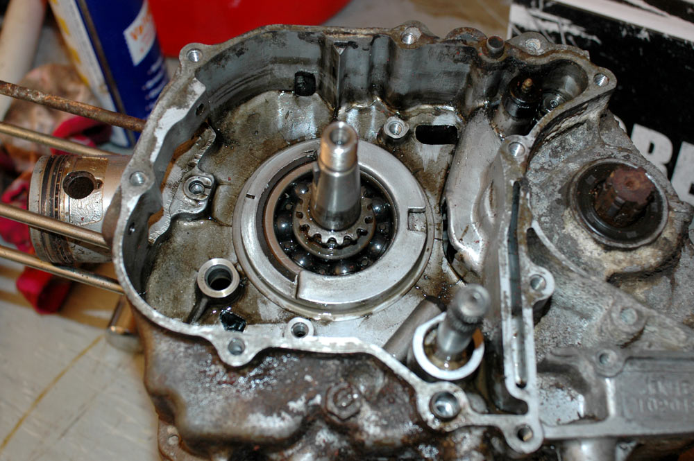
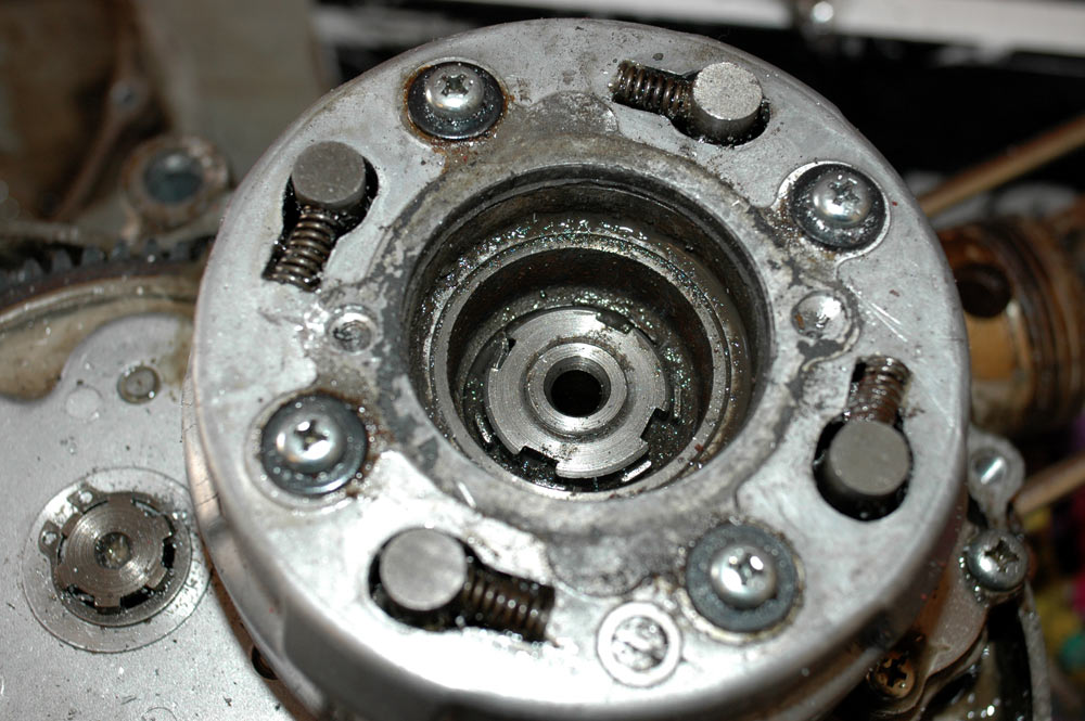
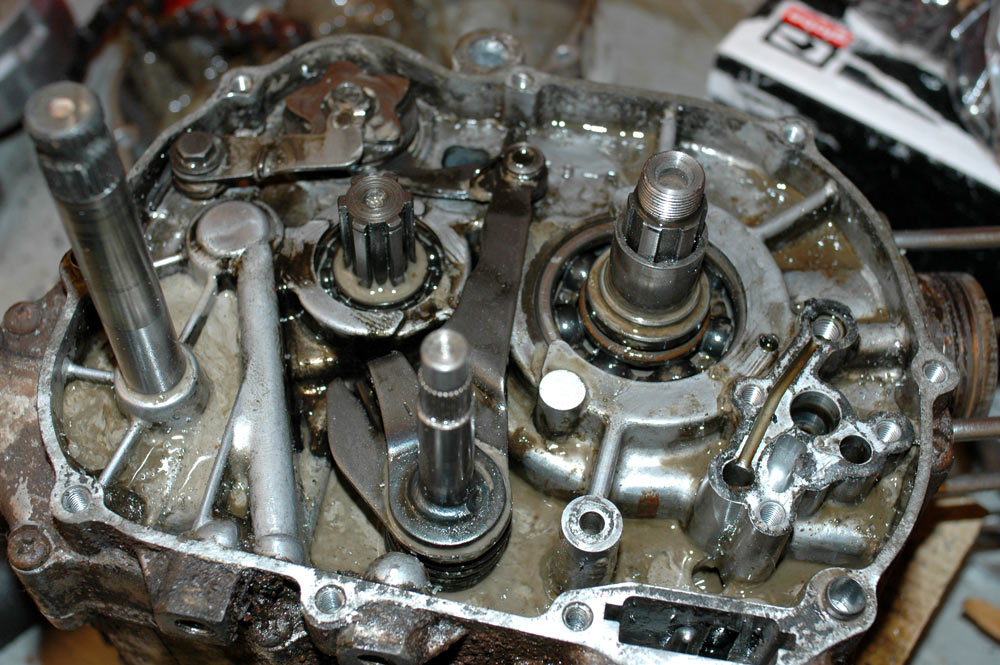
For reference, I've added another view of the output side of the crankshaft. This is mainly to guide me when I reassemble the motor, as I couldn't precisely remember how this all went when I pulled the first motor apart, and promptly pulled it off the end of the crank.
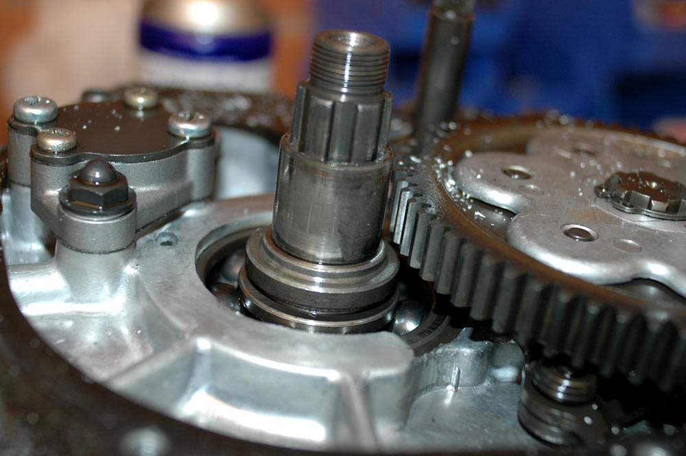
More detail on the drank output side.
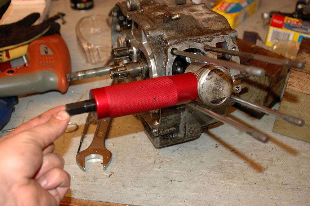
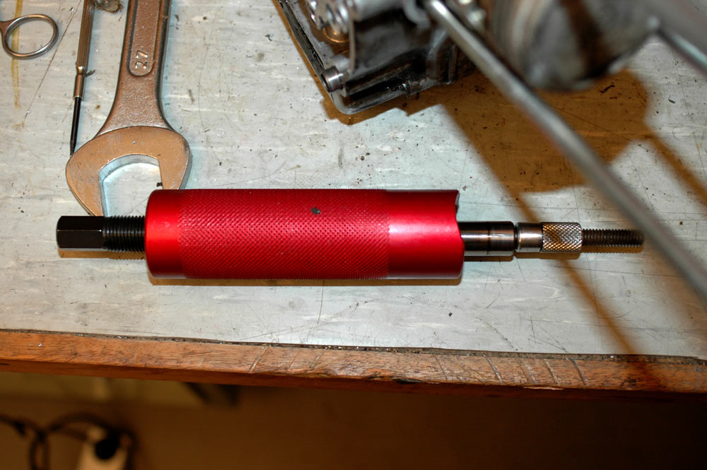
One other task I completed was to remove the piston. For this task I used a piston pin puller I bought.
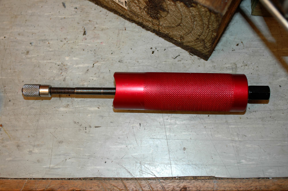
Here's the piston pin puller before I used it.
Theoretically, you can push them out with a soft drift and your fingers - the pin is only supposed to be finger tight. If you can't do that, you can try using boiling water to heat up the piston. If that doesn't work, wait till the cases are split and punch it out with the crank on the bench. You risk damaging the big end if you try to punch it out with a hammer and drift while the crank and rod is still confined by the cases.
The puller is pretty simple - there is just a little collar at the end which is held on by a left-handed threaded sleeve.
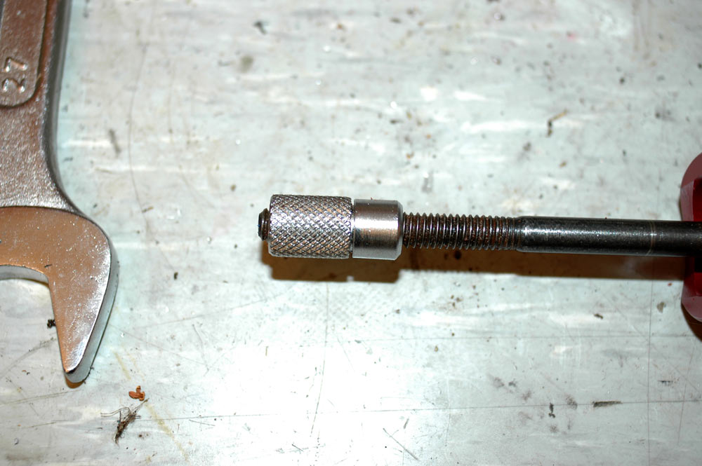
The end of the piston pin puller.
You put that on one end of the pin, take up the slack, push the curved end of the body of the puller against the piston, and turn the big hex-headed bolt at the other end. One could easily fabricate a puller themselves, but I bought this one cheap on ebay.
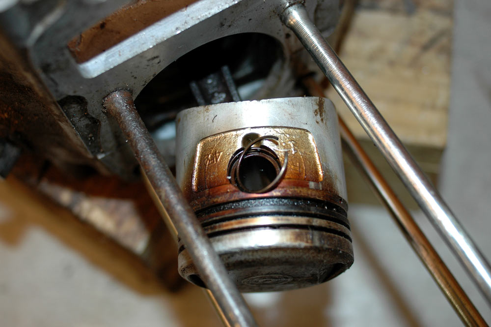
To start with, there are clips at either end of the gudgeon pin.
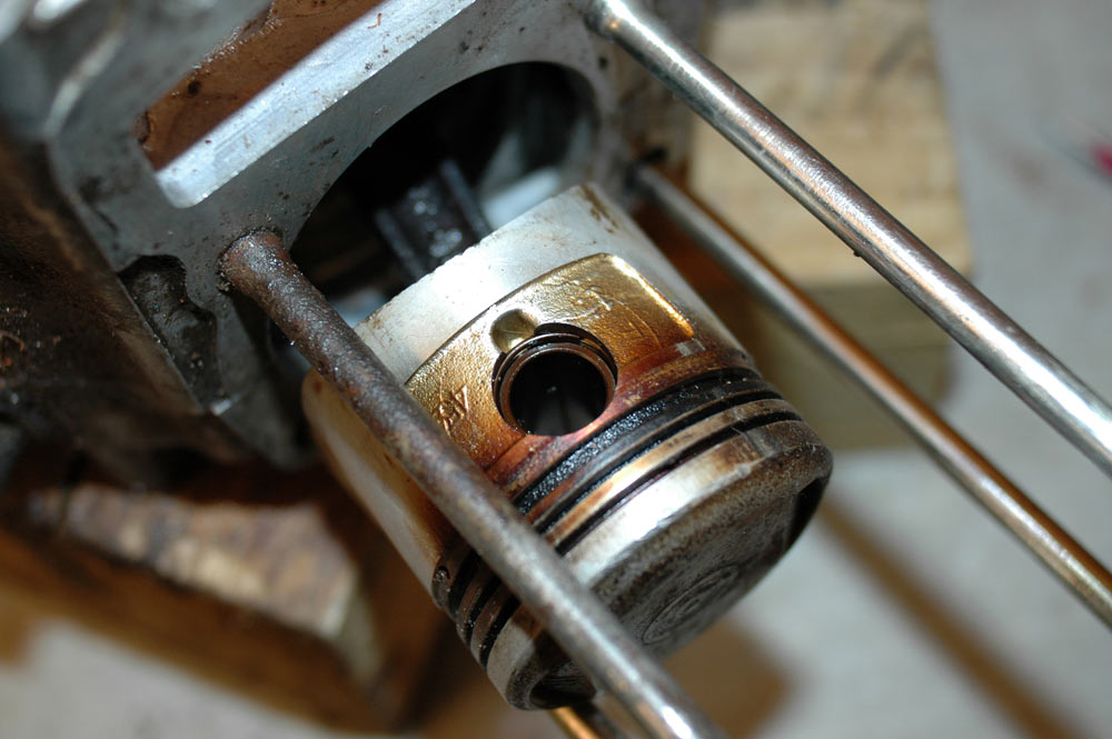
You can just make out the circlip in this picture.
You will want to pull out at least one of these circlips. Usually you pull both out and make it easier cause you can push the pin out either way, but if you can only get one out then you push it out from the circlip in end. A handy hint in getting these out is if you can't easily see the end, put some tape over the skirt of the piston and use the little indent below the pin as an area to lever, using a small flat-blade screwdriver, the circlip out.
Piston circlip sitting in the hole (note it is the circlip from the other side - the circlip for this side of the piston is still waiting).
Using the puller is simple, but I thought I'd take lots of photos just to ensure someone doesn't cock it up due to my poor writing.
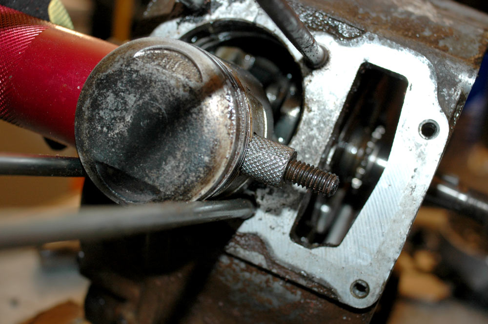
You undo the nut and the collar at the small threaded end of the puller, and push that end through the piston pin.
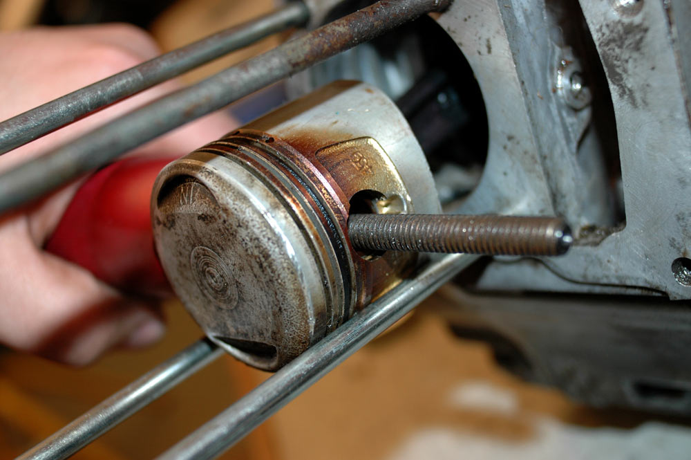
Piston pin puller through the pin.
Next you place the collar against the piston pin.
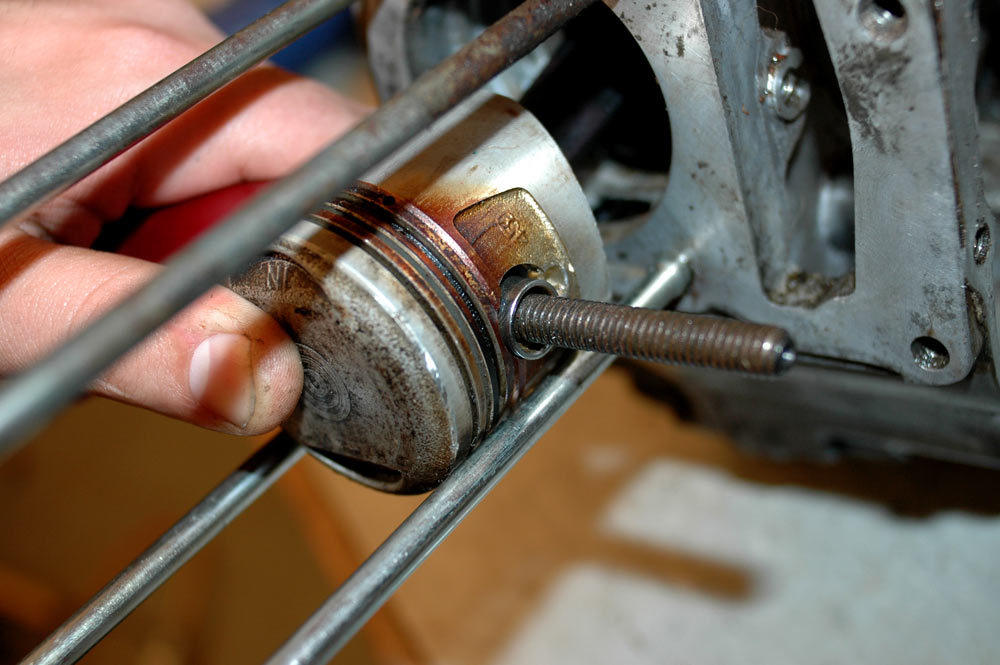
Placing the collar against the piston pin.
You follow the collar with the threaded sleeve/nut/whatever you wish to call it.
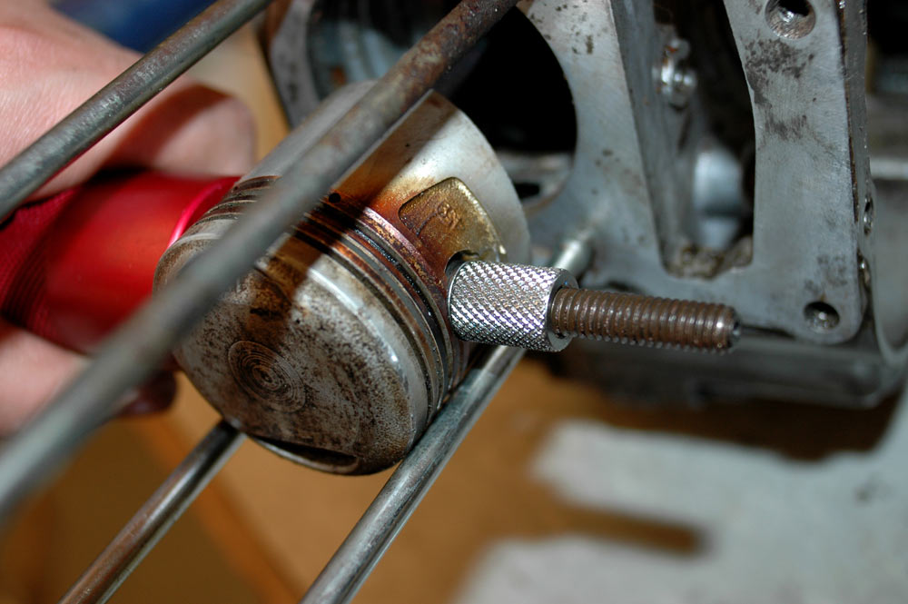
Added threaded sleeve/nut/whatever you want to call it.
Now the puller is all ready to be used.
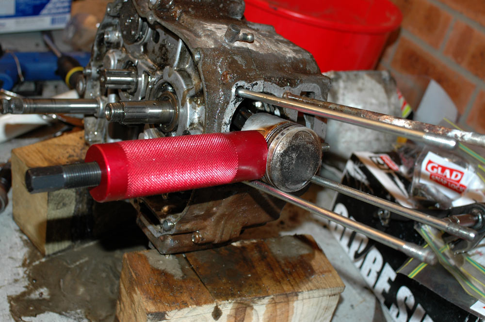
Piston pin puller ready to be used.
You now just turn the hex ended part of the black rod and it'll pull the pin out.
Piston pin puller, viewed from a three-quarter view.
View from the top of the piston pin puller as it works.
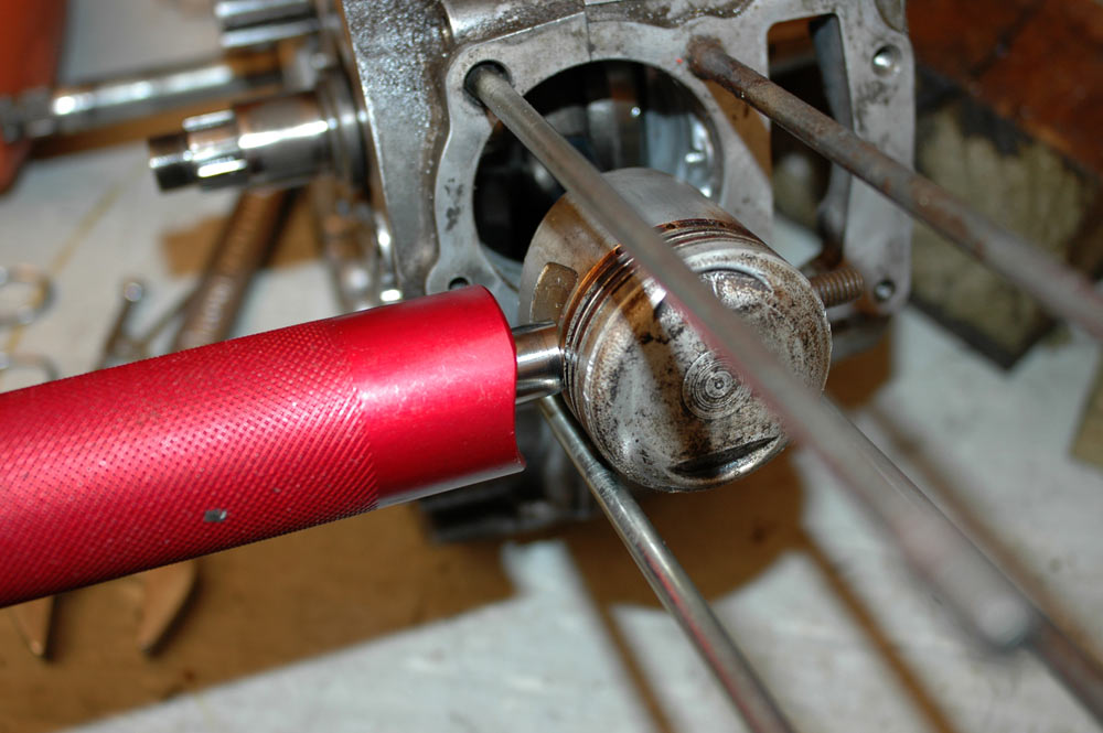
Piston pin almost pulled out.
Once you pull the pin entirely out, the rest of the piston pin puller can be withdrawn and the piston removed from the conrod. You can then admire the effort the puller has made for you.
Piston pin puller with piston pin still on the shaft.
Splitting the cases on these motors is pretty simple once you've stripped the sides of the cases right down. It isn't necessary to pull the piston out like I did above, but I think it is easier to do it then rather than as a bare bottom end on the bench.
As per all of the other cases, they're held on by phillips headed screws on standard motors. They can also be corroded in fairly badly, as I found out. What follows below is a sort of guide to using an impact driver to get these screws out. There really isn't any other way to do it: you can't fit vice-grips on the head of any of the screws and turn them, and if they don't come out using an impact driver used correctly they probably won't budge with a screw-extractor. You could drill the heads off, but then you risk damaging the cases, and you might be stuck with screws that won't come out with a pair of vice-grips to the shaft. What you'll probably do is shear the bloody things off at case level, and then you really are fucked as your only resort is to use an easy-out or throw the cases away.
Top tips for successful impact driving
With that in mind, once you bash away enough, eventually all screws will loosen and you will have them all undone.
There's a couple of other things to undo before you split the cases. First, undo the screw which is into the gear shift selectory thing and pull that off. It is keyed so it will only go onto the shift drum one way. Now flip the cases over so the clutch side is down, and you will notice a cheeky little bolt right near the neutral light pickup. It is a holder for one end of the shift drum. Undo it.
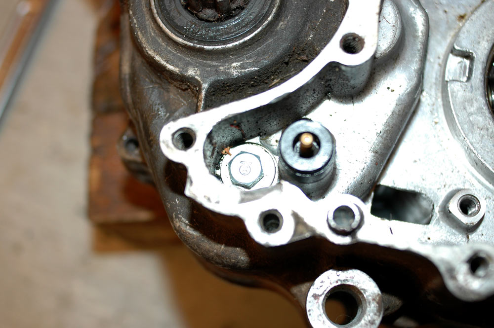
Before you split the cases, undo the shift drum retaining bolt. Neutral light pickup is just to the right of it.
Now you're ready to start to split the cases. If you are lucky, they'll just fall apart. If they don't, DO NOT PRISE THE CASES as you'll fuck up the mating surfaces and they'll forever leak. These are VERY WEAK cases and DO NOT like any prising, so don't do it. Tapping around them, right near the joint, with a plastic mallet helped. Another trick is to spray a bit of gasket-eating compound onto the join as it'll help release the two halves. After a while, and some swearing, they do come apart. It's best if you have the flywheel side down, as it just is easier having all the transmission stuff sit on that side.
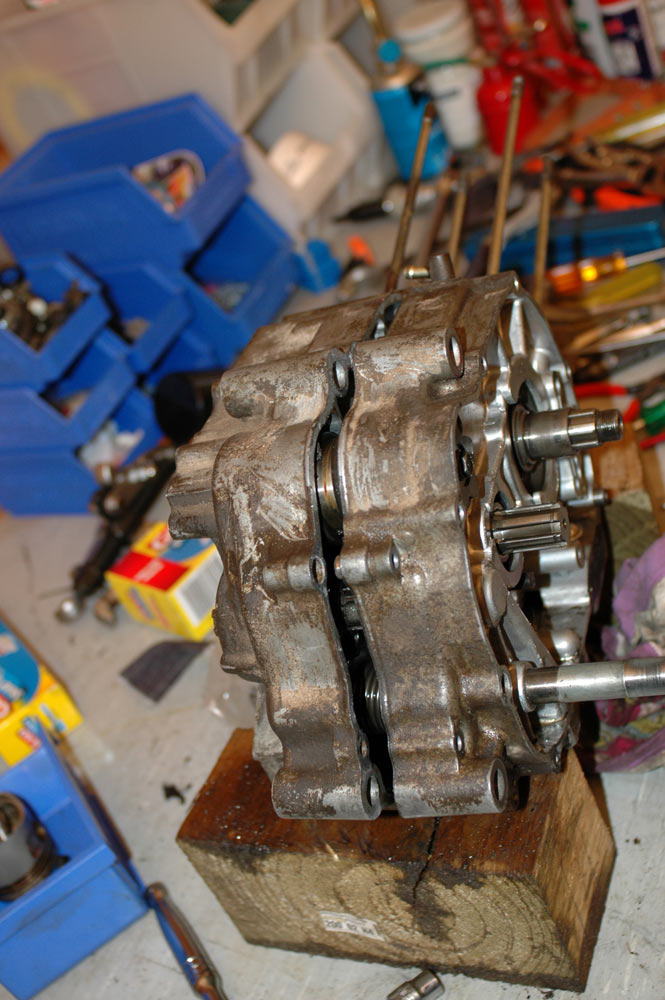
Cases almost split.
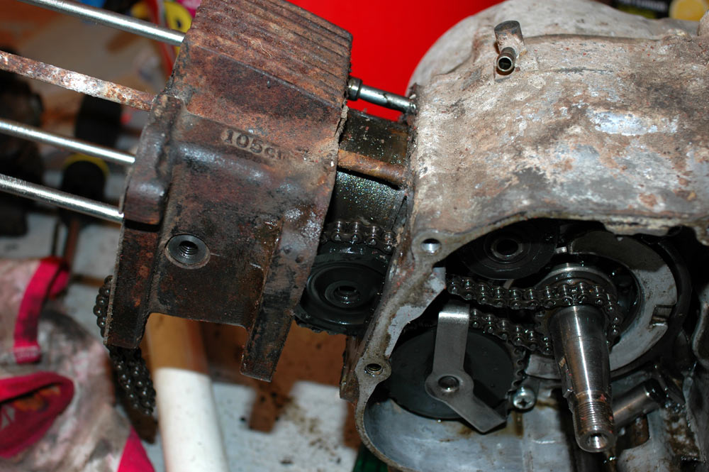
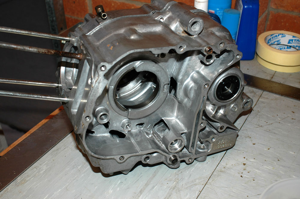
Once split you'll get the joyous sight of the transmission and crank sitting around, waiting to be inspected.
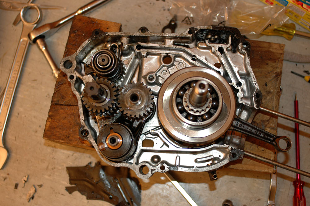
After splitting the case - the internals.
For reference, the shift drum is the bit with the copper thingo sitting on top of it, near the bottom of the picture. The two shafts in the middle with gears on them are the (L) output shaft (countershaft) and (R) the input shaft (main shaft). Above the output shaft is the kick starter. Note that I've actually done this one a bit backwards as I have all the bits sitting in the clutch side case.
The crank is really easy to get out, it just lifts out, so do that and set it aside. Maybe give it a wipe, but also drip it back over with oil so you don't rust anything. Those bearings are bastards to get off (need a crank splitter).
The other joys of splitting the cases is finding the metal flotsam which has been cruising around the motor, doing untold mechanical damage.
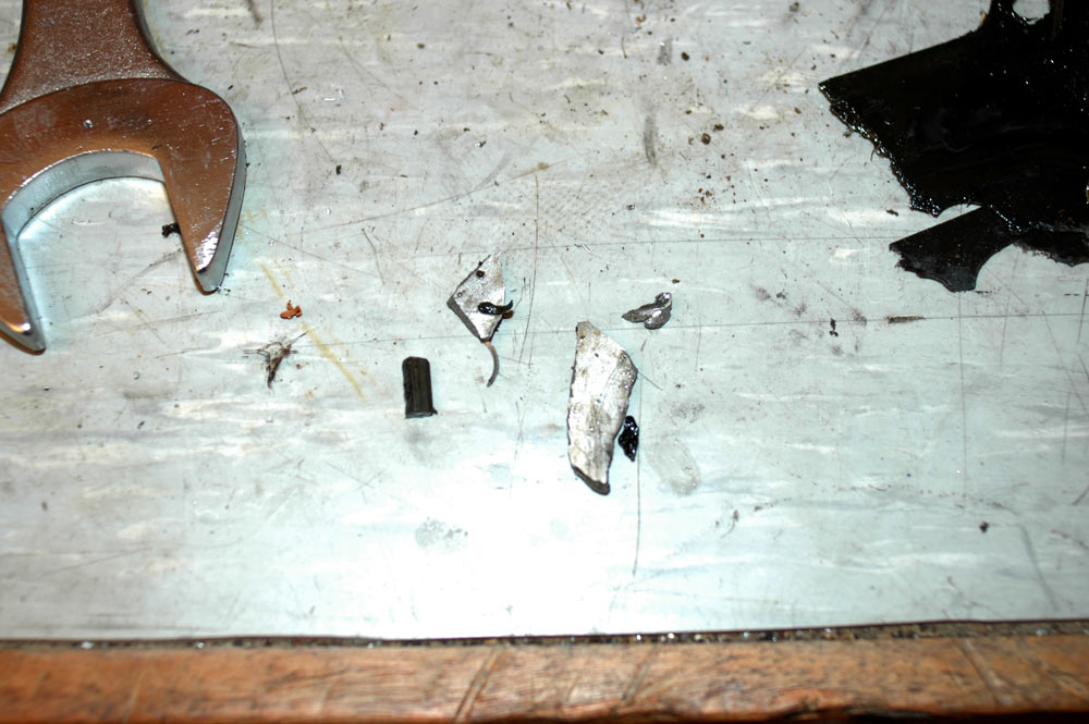
Flotsam from one of the engines. The light coloured stuff is alloy from the case, the dark thing is a gear tooth.
Once you pull the shafts out, you can look for the source of some of this flotsam.
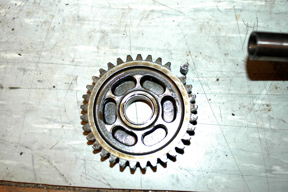
Well, there is your problem sir. Broken off tooth shown for confirmation.
This is a gear which sits at the bottom of the output shaft and takes drive from the kick starter when you kick it over (in neutral, that serves to spin the motor over without spinning the top half of the shaft - note the copper bushing in the middle of the gear in the photo above). It was broken just like this in both of the motors I pulled apart - perhaps it is a weak point of the CT110 design? I know a lot of the Chinese pit-bike motors that are copies of the Honda 50-110 singles have problems chewing up the kick starter setup (when fitted - not sure about electric leg ones).
With that, it's heigh-ho and off to the dealer we go for a new gear. Normally with a broken gear you'd replace both it and the gear it drives, but with the kick starter the gear is only driven when it is engaged, plus the damage didn't seem too much. Finally, you can't just replace the mating gear on the kick starter - you replace the entire assembly which is not cheap.
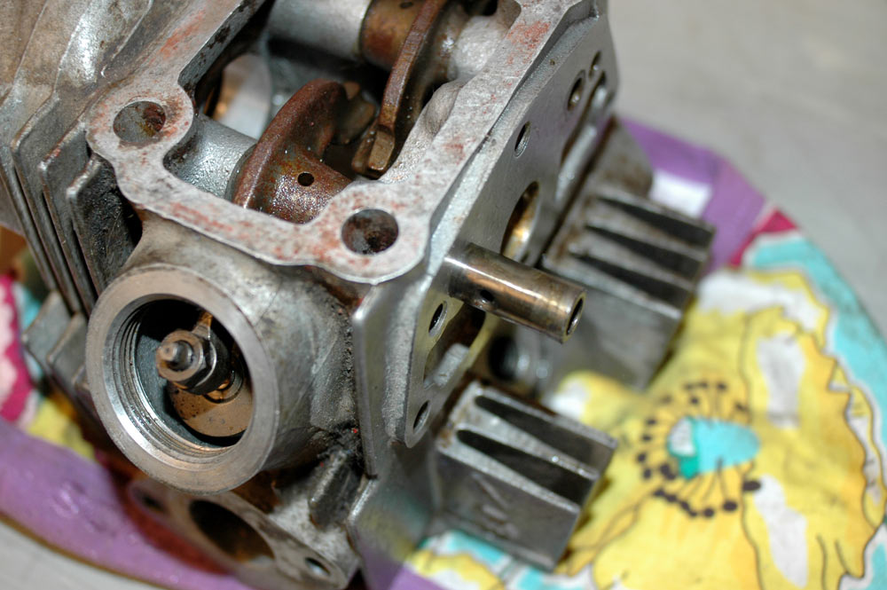
Another fun task is stripping the head down. This is pretty essential, as the valve seals wear really quickly on these motors, plus the camshafts can be prone to wear if servicing isn't kept up - CT110s have small oil pumps and quite a way to push the oil up to the camshaft. To begin with, sit the head on the bench.
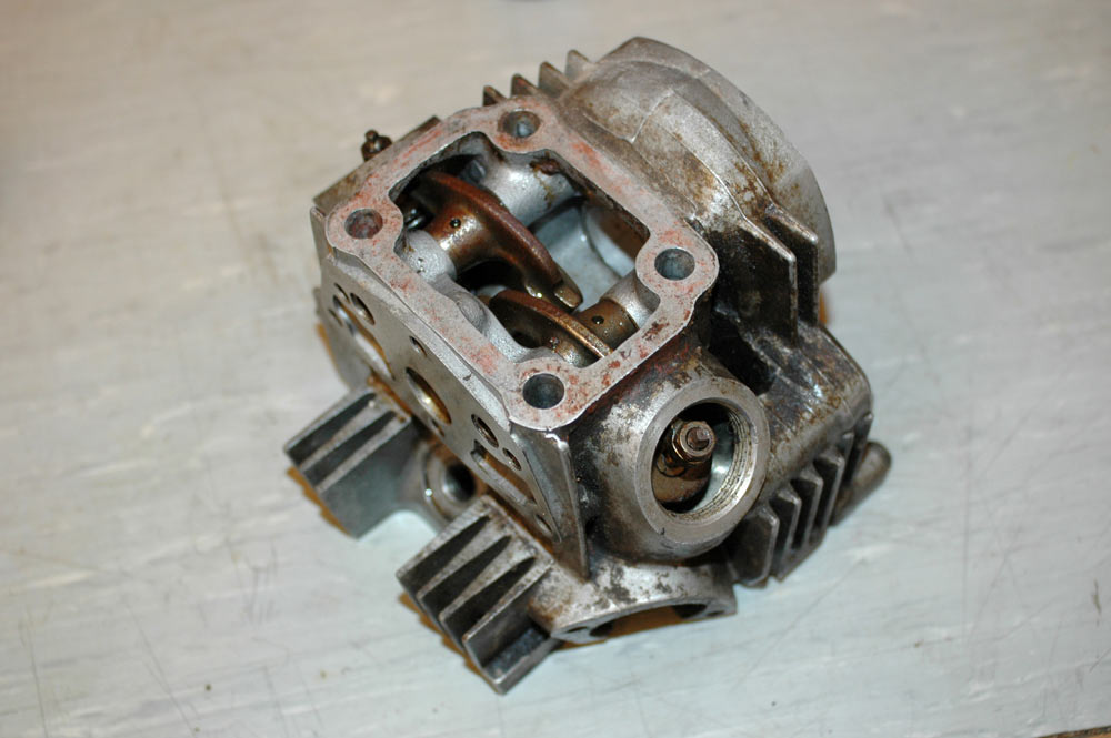
Head before stripping.
The first parts to come out from the head are the rockers. They are held in with little arms. You can't punch these arms out, in fact they're a right royal prick to get out. The suggested method, by both the Clymer manual and the Honda manual, is to tap the side of the head right near the rocker arms and they'll slowly vibrate out.
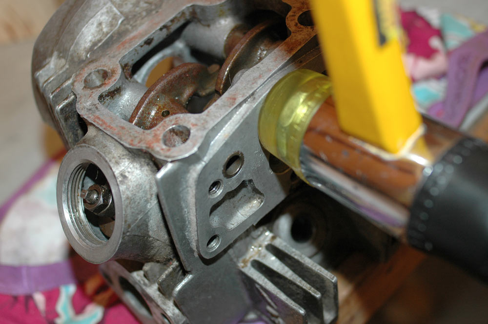
Tapping the head to vibrate the rocker arms out. The intake one here is almost ready to come out.
Once you tap the head about, oh, three hundred times, you'll have a rocker shaft peeking out just enough to grab it with some pliers and pull it out of the head.
Intake rocker arm shaft almost pulled out of head.
Like all things, there is also a bodgy way to do this. Ready an appropriate sized conical plastic masonary anchor and self-tapping screw. Poke the conical anchor and screw into the rocker arm, push it in really hard so it is in tight, then tighten the screw which will expand the anchor and grip the insides of the shaft. It's then just a case of pulling on the screw - the rocker shaft will follow.
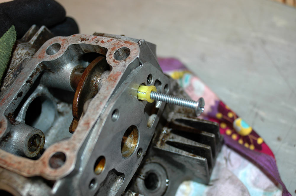
Conical masonary anchor and screw in rocker shaft. Tightening screw = expanding anchor = able to pull out shaft.
With the rockers out, the only thing left to do is to take the valve springs off and remove the valves. You could buy a dedicated valve spring compressor, or do it cheaply with some rough bits of pipe hacked apart to allow access to the valve retaining collets and a rachet clamp.
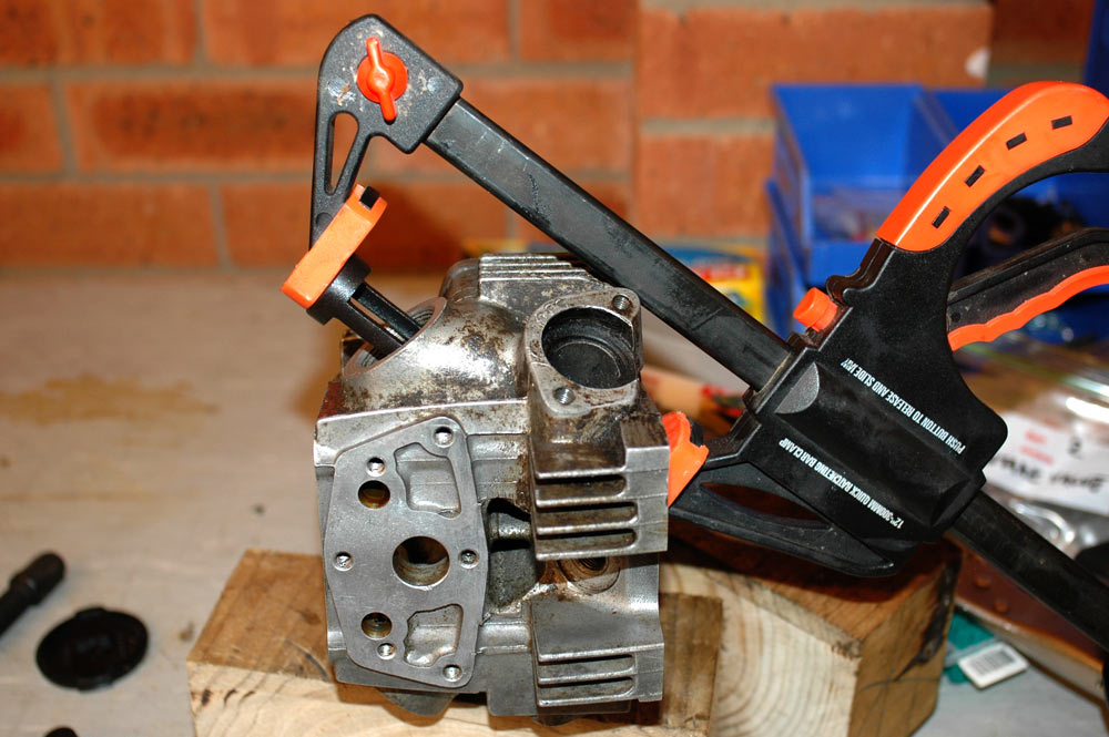
Ghetto valve spring compressor.
Actually, for mine I didn't use hacked-apart valves. I have a cheapo ebay special valve spring compressor which is completely useless, but the removeable ends are still perfect. For the price ($10, delivered), it's worth it even if I don't use 90% of what the kit came with. Anyhow, with the right type of end on your clamp you can depress the valve spring and pull the split collet off the top of the valve.
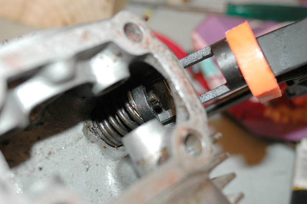
You can see the split collet here. I pull them off using a magnetised screwdriver.
Once the collets are off, you just release the tension on the spring (slowly, if you can) and then push the valve out the bottom of the head. Easy peasy.
Another bit on disassembly is that if you're going to get the cases acid-dipped, you need to remove as much as possible. The main thing most people leave in is the cam chain tensioner. Removing it isn't too hard.
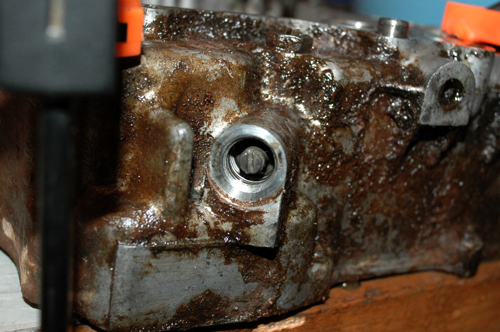
The bolt in the bottom leftish of the picture is the head to the adjust, the nut with the flat screw head through it is the locknut for the tensioner.
Undo the bolt to reveal the little screw which sets the spring tension and hence the adjustment on the tensioner.
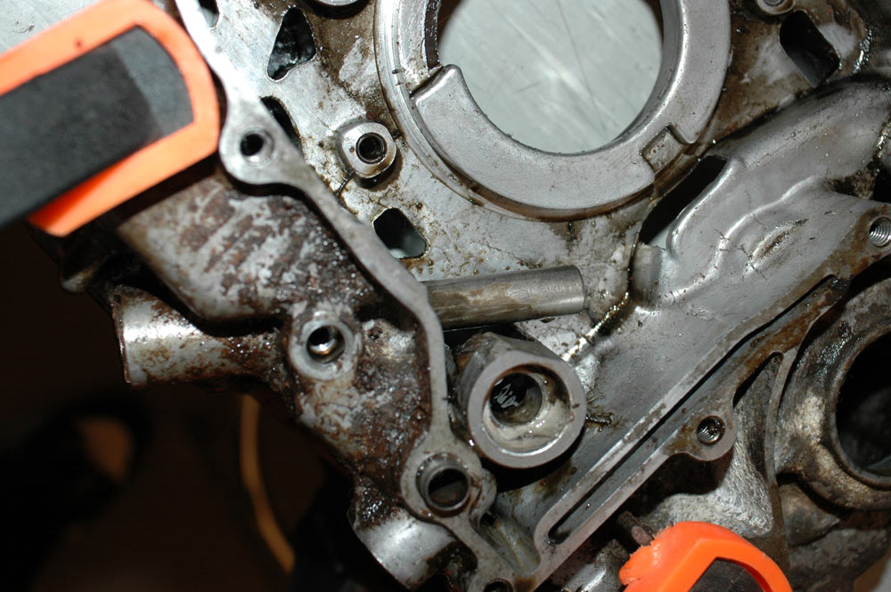
Timing chain adjuster screw.
You undo the adjuster screw, and it and a spring will come out. Now it's time to undo the tensioner locknut.
Tensioner locknut removed.
With that done, you can withdraw the adjuster and lay it all out to make sure you have everything. There should be a adjuster cap bolt, the adjuster, two springs (one coarsely wound one, which comes out with the adjuster, and one more tightly wound one which is in the body of the tensioner), a lock screw and nut, the tensioner body and the little rubber cap which sits on the end of the tensioner.
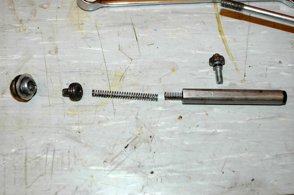
All the parts of the timing chain tensioner.
After that, the case is (hopefully) stripped and ready for dipping.
Dipping the cases is a bit of an artform. You have three major choices here:
I've chosen to degrease the engine cases myself. Why? For one, we're not talking about expensive bikes, and both acid dipping and bead blasting are not the cheapest thing to do. I also think they do not preserve the look of the engine. Bead blasting, even with super-soft walnut shells, still gives a sort of hammered finish. Acid dipping tends to remove any sort of luster which then takes a lot of polishing to get back. Acid dipping also involves soaking your parts in tubs with fluids that have soaked other engines. The dirtier your parts, the later in the cycle they tend to be soaked - with at least one of these cases, they were so dirty I'd have been charged extra as it'd require two dips! When you soak parts with lots of dirty water, you end up with all manner of shit in the oilways. This is fine on a car engine with reasonable sized oilways, but these motors have small oilways.
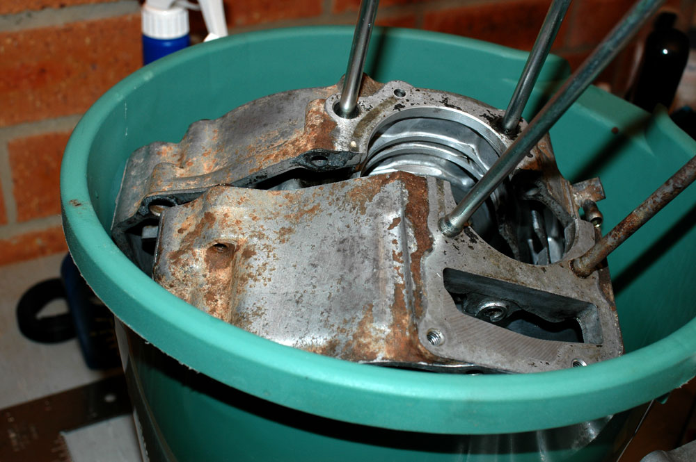
Degreasing by hand it was! This is pretty simple to do, really. I used a 65 L fish tub from a hardware store. It is plastic, reasonably shallow but nice and wide and long. I also used a water-based degreaser, mainly cause I like my lungs and some of the gunk on the engines was dirt-based, which is not shifted by a petroleum-based degreaser. I mixed 1 L of degreaser to 20 L of hot water. The normal mixtures for this degreaser range from 1:15 through 1:70; 1:20ish is what is suggested for parts washing.
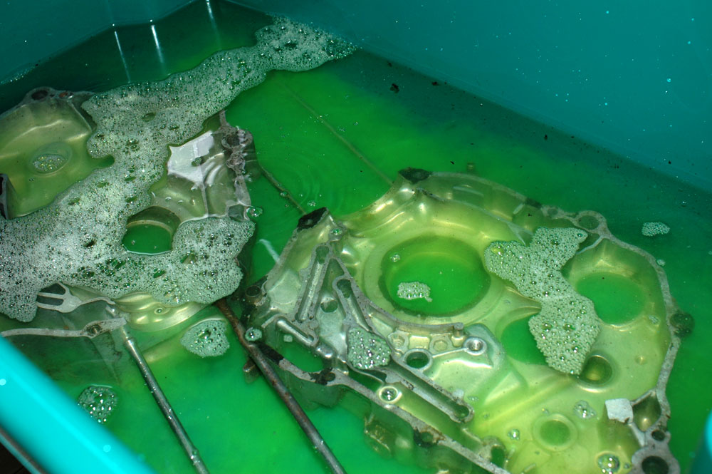
The engine cases for engine #2, soaking away. The tub is green, nicely matching the degreaser.
One of the reasons for soaking the cases this way was to try to preserve as much of the factory Honda look to the cases. Rather than using lots of nasty scouring pads, or wire brushes, I used a tootbrush, a stiffer nylon brush, and some scotch-brite non-scratch scourers. They worked quite well, considering.
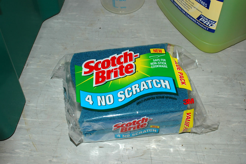
Scotch-brite cleaning pads. They work!
I'll now split the discussion into engines 1 and 2. Just to be different, engine 2 is discussed first (as it was the cleanest, and thus took the least work!)
Cleaning engine 2
Engine 2 was pretty clean, with the hardest things to get rid of some of the grease on the outside of the cases, and some gasket material. The gasket material here wouldn't even shift with my mega-destructive gasket remover, so, it was time for a soak and see.
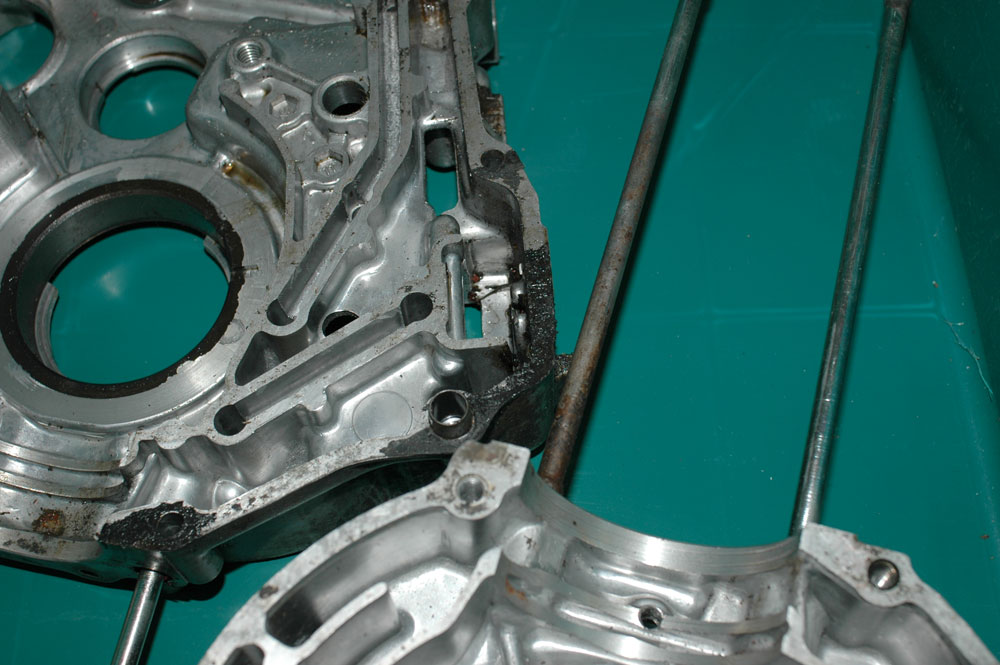
The gasket material on engine 2.
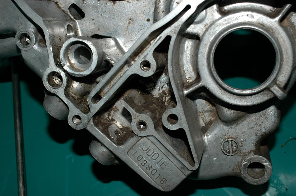
There was also a lot of crap in some of the more hidden areas. No matter how hard I scrubbed with normal degreasers, I couldn't shift this. It was time to resort to a good soaking.
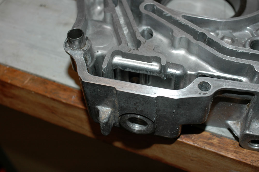
After a good soaking, the cases came up very nicely. Bear in mind that all I used to clean them was time (took 1 hour and 15 to do this), a nylon brush, a tootbrush, a nail brush, and a single scotch-brite non-scratch pad. I took these photos after installing the new bearings and output oil seal.
Shiny!
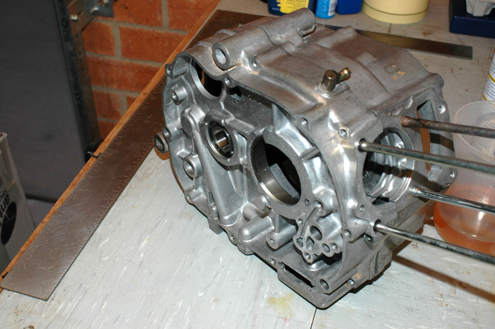
Shiny on this side too!
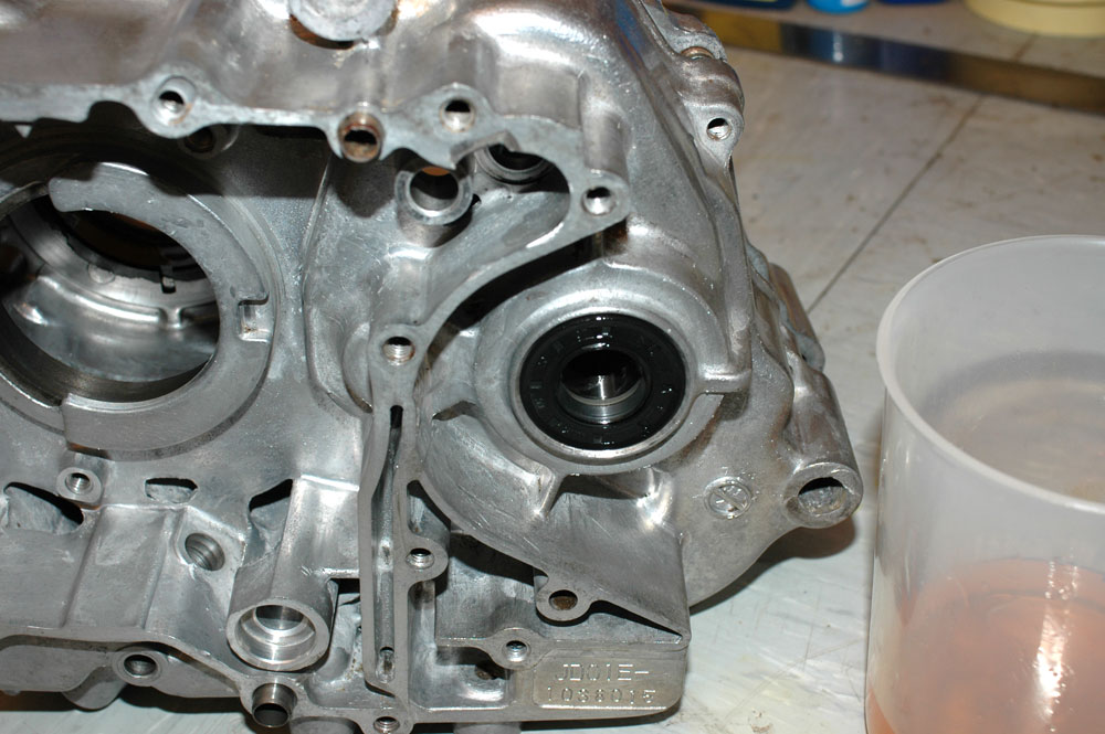
Compare this view with the crap in and around the output area before.
Engine 1
This engine was far, far dirtier. I gave it a preliminary clean using the dirty degreaser solution that I used on engine 2, and it waits for a second dipping to occur on another day.
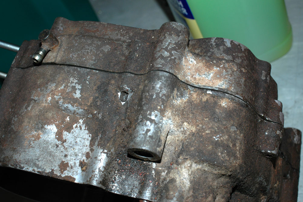
This engine had a particularly dirty exterior
They also had a very dirty interior
The first clean was able to shift some of the major dirt, and at least give me hope that a second clean in fresh degreaser and water would pay dividends.
Here's how clean the exterior of these cases was after the first clean
After cleaning the cases, it is time to look at preparations required for the rebuild.
The first main thing to do is to prepare all of the gasket surfaces. After all of the gasket material is removed by either gasket stripper or soaking with degreaser and scraping the material off, you use some rough sandpaper (somewhere between 120 and 240 grit is perfect) and clean up the gasket mating surfaces. You aren't after a smooth polish, but a reasonably uniform surface with no obviously huge high-spots or anything like that.
Here you can see a nice and clean segment of a gasket mating surface. Compare this to the same area before I soaked it in degreaser
You'll want to make sure you clean out as much of the fine metal shavings that result from this process. This is especially important in oilways - you don't want to be sanding your new bearings once you fire up the motor for the first time! Also, alloy is non-magnetic, so it won't even be picked up by a magnetic sump plug...
The assembly of the clutch side is pretty simple. I don't have too many pictures, but I'll show the traps for young players as we go.
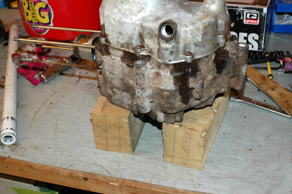
The first thing you'll want to do is set up to join the cases again. You grab the clutch side of the cases, and place that on some blocks.
Stick the crank in (after cleaning it up, and suitably oiling the bearings).
Put the kick starter in, ready to mesh with the gearbox.
Grab all of the transmission stuff, and put that in. You basically need the shift drum, the input and the countershaft all meshed together. Best to set it up in neutral. Make sure all the thrust washers are in the right place when you do this. This is why you document everything you pull off the bike, and keep it together as much as possible.
Once you have that, stand the motor up. Hold the gearbox internals and see if you can turn the shift drum and hence engage all of the gears. Spin the input shaft and see if you can get the output shaft to spin at different speeds by engaging different gears. If that works, you are ready to join the cases.
Lay the right side back down. Place a fresh gasket on your nicely cleaned up gasket surfaces, and keep it in place with dowels. Slowly lower your left-hand case side onto the right-hand one. Everything should fit in really nicely. If you have to tap it in place with a hammer, you've seriously fucked something up.
Once you've got it mated and sitting on the dowels, before you bolt it up, check that you can engage gears still by playing with the shift drum. If you can, you're good to bolt up. Remember to do the bolts or screws up finger tight, then work in a criss-cross pattern all the way around the case. Take your time, do it up a small amount at each time lest you snap a bolt (bad) or warp a case (worse).
With the case halves joined, you're ready to reassemble the shifter stuff. This is pretty easy, just don't go forcing it through the case too hard. You insert it from the right-hand (clutch) side.
Once you have the shifter in (which is easier with the gearbox in neutral) you can also bolt up the little bolt that located the shift drum on the left-hand (flywheel) side of the motor. Don't do this up fully tight yet, you may need some wriggle room to make it engage gears properly.
With the shifter in place, you can stand the motor up normally and grab a gear lever. See if you can't get the motor to engage gears. You might need to rock the input shaft to get it to flick up into some gears, and do the same but on the output shaft to go back down gears.
With it engaging gears properly, shift it back to neutral (which is all the way down!) and nip up the bolt that locates the shift drum. You can also put the neutral switch in. Although they just can be pushed in, I used a really small slather of silastic to make sure it would stay in place even if I tugged hard on the wire.
With that done, you can now put on the primary drive gears.
After that, it is time to put the clutch on. There are two ways to hold it in place while you torque up the centre nut. One is a proper holder (like a strap holder you'd use on an oil filter), the other is to put a rag around the cylinder base at the top of the cases, and put a big-arsed screwdriver through the piston pin end of the gudgeon pin. When you do this, as you tighten the clutch you'll pull the screwdriver down onto the rag on the cases. Torque the nut up, and the clutch won't spin. If you don't put a rag down, you will mark the gasket surface at the top of the motor and that just plain sucks, so don't do that.
Hopefully you remembered to put the locking tab behind the clutch nut, otherwise you have to undo it and put it on. Flick one of the tabs in to hold against the cutouts in the clutch nut, and it'll be nicely held.
The clutch outer place now goes on. Place the centre bearing in that too.
Onto the centre bearing, you can place the lower part of the clutch engaging mechanism. When you do this, you'll want to also ensure that you have aligned the clutch release lever appropriately - it needs to be in line with the shaft and the oil return pin...
Clutch release lever, aligned correctly
... and not a spline off one side or another...

Clutch release lever, aligned incorrectly
In regards to the clutch oil return pin, it has a spring behind it. Make sure you can press the pin down against this spring. If you can't, you won't get the clutch cover to fit onto the case.
Make sure you can press the oil return pin down!
You can see in the above photo the nifty allen-key headed screws I have for the clutch outer plate. Should make it much easier to service and clean out the oil path through the clutch!
The other thing that needs to be remembered is to put the clutch release spring down.
Clutch release spring
Sitting atop this spring is a series of balls. The top part of this release mechanism sits against the adjuster in the clutch outer cover. Fully screw the adjuster screw into this, and remove the nut and the protector plate. There's a little o-ring that hides under here, and is the cause of many oil leaks. Ensure you replace this o-ring.
New O-ring placed on the clutch adjuster
With that done, it's just a case of putting the dowels into the case, placing a new gasket on them, and putting the clutch cover on. Wriggle it on slowly, ensuring you don't tear the kickstarter seal. Also, the shift lever locates into a fairly tight hole in the clutch cover, so make sure this is engaged before heaving on the cover. With the cover on, you can tighten up the bolts. Do this in a criss-cross pattern, tightening each bolt up a small amount each time.
A newly assembled clutch side of the motor