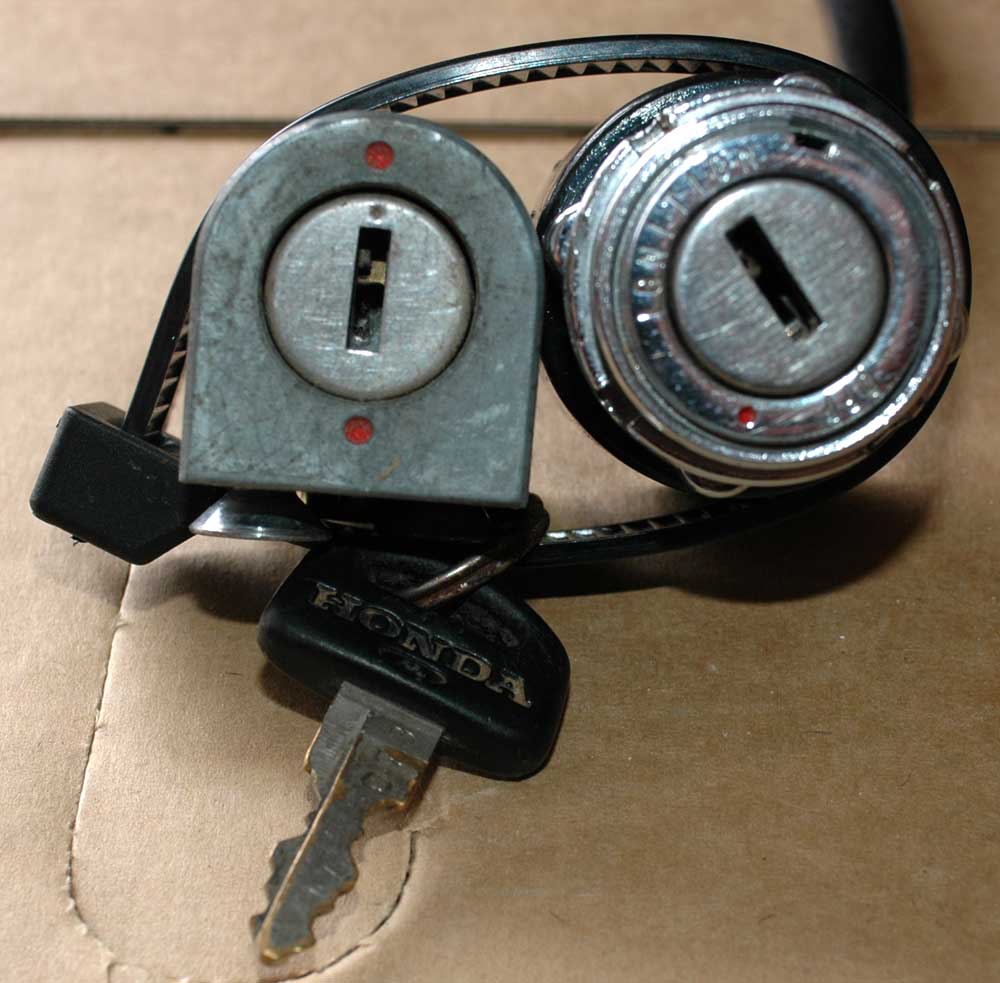
Steering lock (left) and ignition lock (right), secured together with the key cause I hate losing things which would piss me off to find the same setup again.
The Wenga Postie Bike Project -> The rebuild -> Frame and controls
One of the things that I've always insisted with this rebuild is that we use a proper postie bike key. Most people hot-wire the posties so that the ignition key isn't needed. Well, I don't care, I want it to be somewhat original in this regard. Fortunately, one of the ignition switches in the parts we bought had a working key, and even better, electrically it seems to work correctly too.
Postie bikes don't just have an igition switch, they also have a steering lock which mounts on the bottom of the forks. In the group of parts we bought, there were a total of 12 steering locks - a few mounted on forks, but mostly just floating free in a box. So, with 10 minutes to kill, I sat down and managed to discover a lock which worked with the key for the working ignition lock. Score!
Steering lock (left) and ignition lock (right), secured together with the key cause I hate losing things which would piss me off to find the same setup again.
I'll probably use somewhere like hondakeys to get a key for the other ignition lock and a corresponding steering lock - the lock is actually worth money then. With a locksmith costing between $30 and $50 to rekey an ignition to a given key, it's cheaper to buy an old-stock genuine key. Also, most locksmiths seemed to not want to rekey a steering lock, but even if they would, that's another $30-$50 for a working lock set...
Polishing parts is something I do as I go along and find the best bits. The handle-bars are clamped onto the top triple by little silver clamps. I grabbed the best two and polished them up to see how it looks with the chrome handlebars I've selected to be used on the bike.
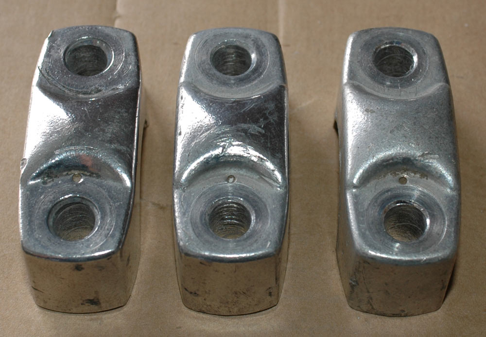
Handlebar mounts. Polished ones (obviously) are the two leftmost clamps. Right shows an unpolished clamp.
The mounts still have some little chips out of them and some grease I still need to remove, but they look a lot better. Gives me some confidence that everything can look really nice when I bolt it all together.
One of the things I'd really like is a set of OEM grips. Found an auction on ebay for new ones, complete with part numbers. It would appear one side is 53165-430-000 and the other 53166-430-000. I would presume that one is the throttle control and the other the left-hand side, as the internal diameter of the throttle side should be a bit bigger.
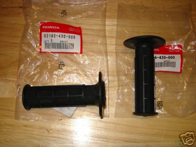
OEM grips - Honda part numbers are 53165-430-000 and 53166-430-000.
Not sure if I'll go for the auction (it's in the US) or if I can get them cheaper through a dealer here. Knowing the part numbers really helps though.
One of the things that I decided was pretty important was to put new head-stem bearings in. Of all the frames we went through as part of the group buy, one had destroyed taper bearings, three had the normal Honda-issue unconstrained ball-bearings in crappy race, and two had the ball-bearings in rings in small races. I decided I wanted taper bearings - only the best would do. Thanks to a place on ebay, I was able to get bearing kits to put new wheel bearings in, plus get some nice taper bearings for the headstem. The bearings are packaged up by All Balls Racing, which is a name I appreciate; they're just good quality Japanese bearings, selected for size and priced about as cheaply as I can buy them here, without having to disassemble first. There's also a trick with the CT110, in that the diameter of the headstem is a little bit thicker for the bottom bearing, so you have to be very careful when selecting taper bearings - another reason to find someone who has already done the R&D to work out what fits and works!
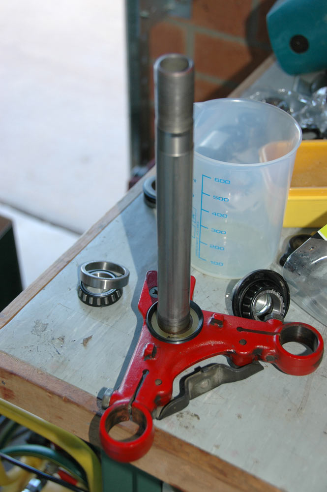
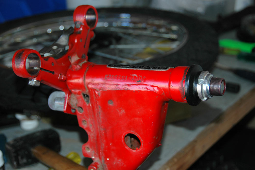
Here you can see the head stem and the bottom part of the triple clamp. Note the thicker bit right near the bottom, plus the narrower diameter at the base of the threaded parts. I think the diameter difference is about 2mm, which must be reflected in the internal diameters of the taper bearings.
Already installed on the head stem shot above is the bottom grease seal. Gotta make sure these are on there, lest you end up with grease everywhere once you assemble it. You can also see on eof the bearing races and taper bearings sitting off to the side. A closer look might be in order though.
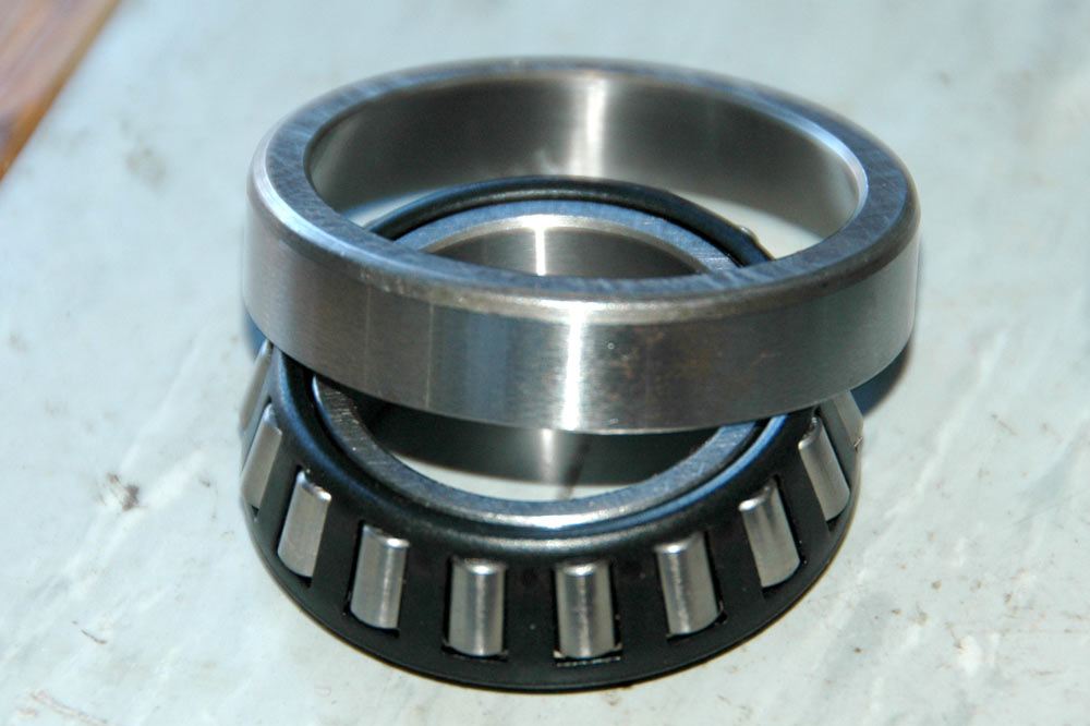
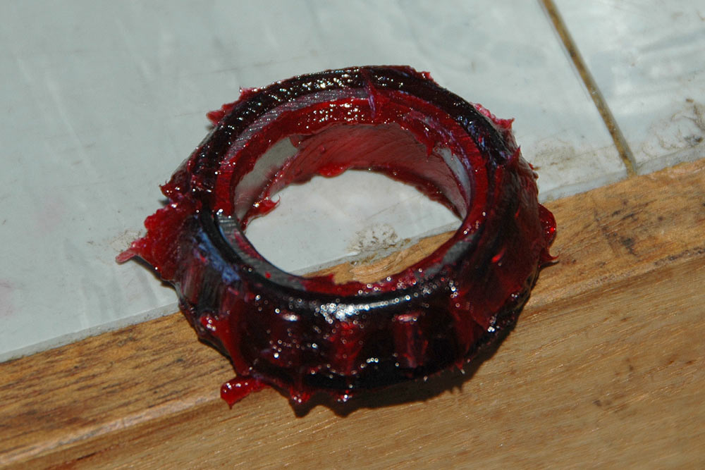
Here you can see the bearing race (top) and the taper bearing (underneath).
Lovely pin-based roller bearings these. The bearing race is thicker than even those used for the captive ball-bearing types, although the CT110 frame neck is deep enough to accomodate these bearings (sort of - the top race sticks out a bit but all gets covered up in the end and works fine).
So, first things first. The old bearing races need to come out. For this, you'll want a long punch. I didn't have one, but I did have the threaded rod from a car spring compressor. Normally you'd use a brass drift, but I like living dangerously. I didn't damage anything, in fact the old bearing races came out fine and were of good enough condition I'll probably sell them (cheaply) as used but reasonable items.
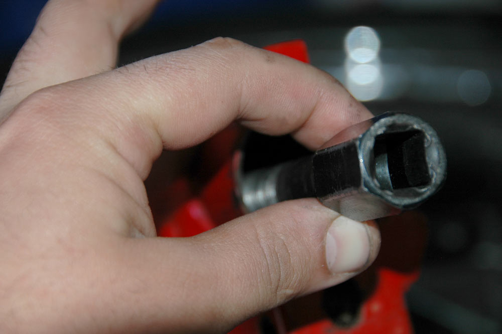
Here's how to drive out the race. Stick a drift in, tap one side, move around, tap another side, and just keep doing it till it pops out. You need to be forceful but don't tap it too much on one side, or else it'll end up rather off-kilter which makes it harder to drive out and can damage the frame's headstock.
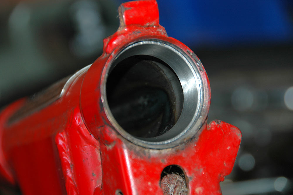
Once you drive out a race, you can see where the new race will mount.
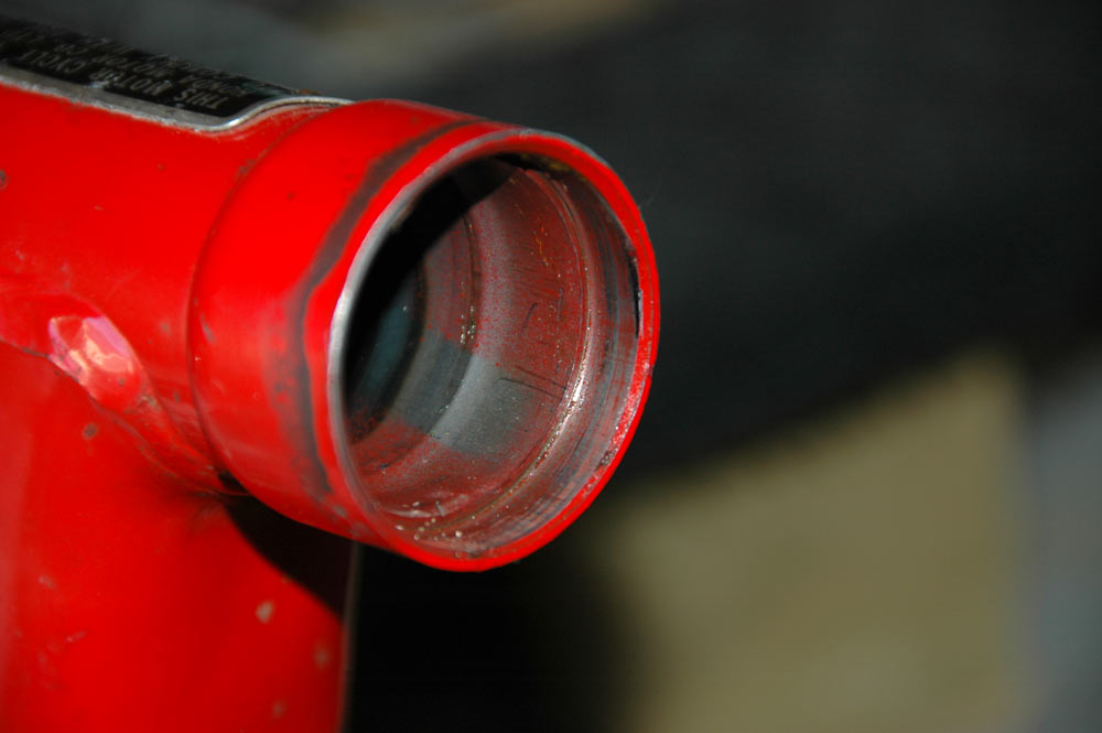
The indentation at the top is where the race mounts. This is the top race mount - the top of the top race mount will sit about 2 mm proud of the headstock tube, but the nut that does up the headstem has enough of a dome shape to cover this. It is apparently in the design of the bearings and the frame to do have it this way.
After driving out both races, we can sit one of the new ones in.
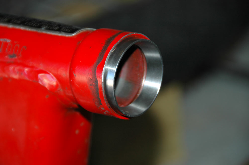
Here's the race sitting in position, ready to be driven in.
You want to drive it in nice and carefully, keeping it as even as possible. In the photo above, you can see I first need to tap the race where it is highest in the photo, then work my way around. At some point, you won't be able to fit a hammer in directly, and need to use a suitable large diameter drift. By suitable, I mean the right diameter. I found one of my 30 mm 1/2" drive sockets fitted pretty damned well, actually.
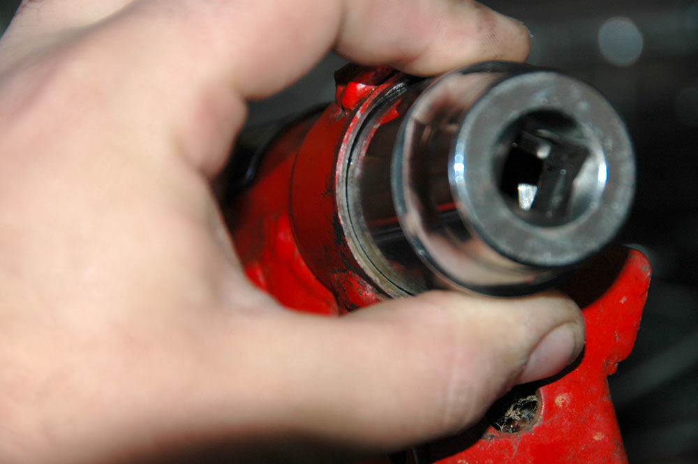
Driving in a bearing race.
Again, be careful to drive the race in nice and straight, and take your time. Once it is in, stand back and admire how nicely you got it in there with minimal swearing. The exception to the swearing part is when you use a 5 lb mallet and miss the drift and find your thumb.
Bottom bearing race, sitting in the headstock.
Now the race is in, I like to put a bit of grease onto the inner part, just in case I don't pack the bearings properly. It's nice to have some insurance. Assuming you got good seals with your bearing kit, you can't really pack too much grease into the headstem!
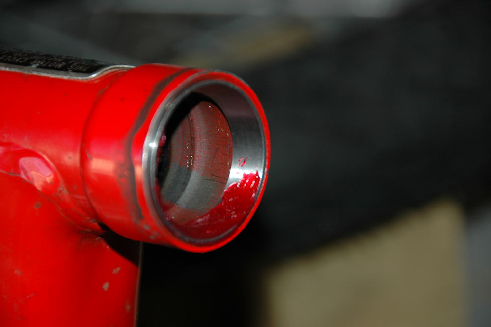
A slather of grease onto the bearing race, just in case. Here you can see the bot of the top bearing race sitting proud - again, this works just fine once you tighten it all up.
You also need to pack the grease into the bearings themselves. Drop one into your handy tub-o-grease.
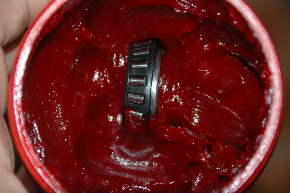
Bearing in tub-o-grease.
Packing requires you push a heap of grease into the bearing. Best done in the palm of your hand. Note, it is hard to pack a bearing and operate a full-sized SLR camera.
Here's a fairly well-packed bearing. Lovely!
After this, all you do is put everything onto the head stem in the right order, push it through the headstock of the frame, and tighten up the nut at the top of the headstem tube. You're supposed to do it up with a small C-spanner or an appropriate pin-punch thingo. I just put a rag around it and do it up with vise-grips.
And here's the headstem assembled.
For how to put the front forks into the bottom part of the triple clamp, head over to the front suspension section.
One of the things I wanted for this project was chrome handlebars. Usually, CT110s will come with black handlebars and I think they look a bit crap. Fortunately, some early CT90s came with chrome bars, and they're interchangeable. The chrome bars I had didn't have any switchgear on them, unfortunately, and no wiring in them either. For those that don't realise, the wiring from switchgear to the rest of the wiring loom runs through the handlebars.
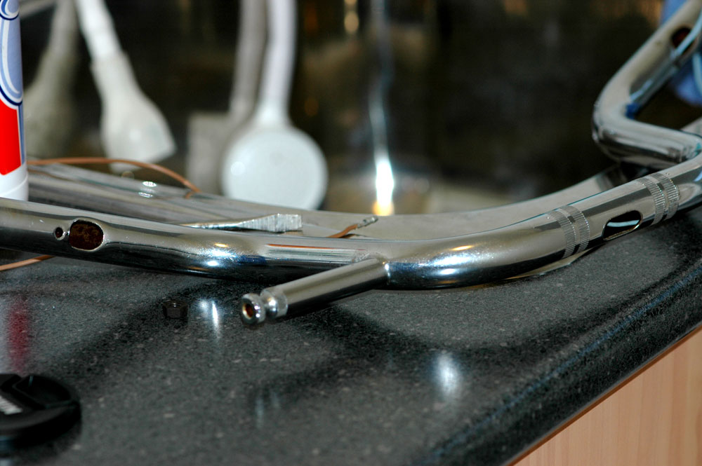
The holes for the wiring are obvious on these bars.
For more details on how you deal with the wiring problem, head over to the wiring page.